Pages on the site

Sunday, 27 January 2019

Dry Build - Footrests

One of the item's I'd tripped up on while putting the crankcases in was the footrest bar. I'd not found the spacer that serves to separate the gearbox plates - or rather I had, but I thought that someone had mixed them up as the spacer I had was too short.

Anyhow, planning to replace the missing engine & gearbox fasteners with stainless I thought I'd set about making the missing spacer, so I bought some 3/4" 303 stainless round bar.

Then, of course, I found the missing spacer bundled up with the footrests and another footrest bar...


Oh well, I thought, I'll use that stainless bar at some point, resolving to replate the original spacer - but when I went to assemble it I found it was rather mangled, so I've made a new one:


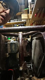
This is designed to fit quite tightly between the gearbox plates and frame tubes, just as the front engine plate assembly and crankcases fit between the frame tubes at the front. I had to spring the frame tubes apart to get those in, so I made this frame spreader out of an M10 turnbuckle make it easier to avoid damaging the paint when I come to assemble it for real. I didn't want to be prying freshly painted tubes apart with a screw driver or a crowbar:


As you can probably tell, the centre of the turnbuckle was shortened and welded up, while the screws had both hook and eye removed and 3/4" ply blocks glued into blind holes in the plywood block. Here it is in place under the front engine plates:


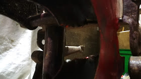
Spacer fits perfectly now:


Tuesday, 15 January 2019

Dry Build - Tool Box & Voltage Regulator

Last night included a bit of dry building activity around the toolbox, regulator and horn. I added the primary case and the clutch cover to understand the space and fastener requirements.

The toolbox hangs from one of the seat mountings using a bolt passing up through the top of the box, through the seat mounting and into the seat - all quite straightforward.


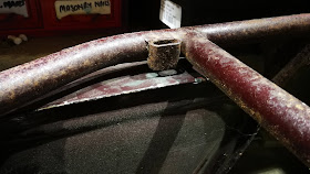
The other fixing point is this tab, beneath the toolbox which allows the toolbox to bolt to a mounting on the frame. This tab is shared with the horn.


Here's a puzzle: Ariel do not list a separate horn bracket for 1958 and here's why - the horn bolts directly to the toolbox tab as shown in MickD's picture below. I don't have those holes on my toolbox! The swinging arm toolbox carried a -54 part number through to the end of four stroke production, so I must have an earlier incarnation of the same part, designed to be used with an Altette and not the Lucas HF1441 horn used in 1958.

I will have to make an intermediate bracket, or modify my toolbox.

Post script, April 2019: This bracket was made here.


My Lucas HF1441 horn, for the FH.


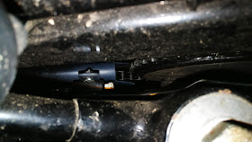
Here's a Lucas voltage regulator fitted in position behind the toolbox - but this is the 40W MCR1 regulator, smaller than the correct RB108.


Here are two views of the large void from above:


And behind, complete with an up the nostril shot. Sorry about that.


A view from the front:


Monday, 14 January 2019

Dry Build - Battery Carrier

It's a work day today, so there's only a few minutes available to play with old motorbikes. Even so, we can look and do a little bit. Here's the state of play:


The next bit to look at is the battery carrier and toolbox. Help from Mick D on the AOMCC forum reveals that the voltage regulator sits behind the tool box, so we might have a look at that later - but we are getting ahead of ourselves here.


The battery carrier is screwed to the top of the primary case with these two special screws - two of the few fasteners I have with this kit of parts. The upper fixing is the sidecar mount, and we will have to order the big nuts for that from Acme Stainless.


Today has also revealed another job:


A broken 1/4" BSW screw.

Sunday, 13 January 2019

Dry Build - Primary Case & Chainguard

The primary case and front chain guard were an area which I had difficulty visualising. The chainguard bolts to the horizontal frame gusset using two folded ears and two round head 1/4" CEI screws:


The chain oiler goes down here somewhere:


At the bottom, a lug retains the chainguard to a stud on the primary case


The chainguard is shaped around the frame gusset:


Looking through the sprocket hole, one can see the damage wrought to my chain guard which I thought was to allow it to be removed without taking the chain off. Consultation with the AOMCC experts reveals I was wrong about that - apparently to get this guard off, you have to remove the gearbox sprocket; it's cut like that to allow the mainshaft to pass through and to allow you to remove the chainguard without taking the sprocket off. I guess I would have realised that if I had put my gearbox in...


Here is the back of the primary case. That long 1/4" stud is for the lug at the bottom of the chain guard:


With it all together, we have a foul condition. On my SQ4, those nuts are half nuts - Ariel did not list the standard nuts & washers against specific sections of the parts lists, so we must use our common sense here. I think I will machine the studs & nuts short in this application, but several of the good folk on the AOMCC forum (thanks Simon, Steve and Mick) tell me that their machines have full nuts here:


Here is the chain guard lug on the 1/4" primary case stud, and primary case on the slim section at the end of the gearbox lower pivot:


We need to start getting these parts bolted up tight to understand what fits and what doesn't. To that end, I've ordered some 3/4" round bar in 303 stainless to fit the footrest bar.

Interesting that the 1958 bikes have this oil flinger to prevent oil getting on the clutch, or escaping from the primary case:


Dry Build - Oil Tank & Air Filter

A bit more time this afternoon, and we can hang the oil tank in place:


The tank is supported on two 1/4" bolts at the front:


And one 5/16" bolt at the rear. Obviously these fasteners are not the right length...


The oil tank is going to make that seat bolt very difficult to get to. I guess the seat goes on first:


The air filter hangs from the sidecar mount using a special nut, with the batter carrier on the other side in common with Ariel practice since before the War.


The air filter is tied to one of the gearbox studs at the bottom:


Dry Build - putting the crankcases in

So, moving on at pace you might remember the gearbox plate with the missing stud. Ariel were quite careful in this area, as one end of this stud is quite difficult to get to and the upper gearbox studs have to be loosened for primary chain maintenance. Way back before the war, these studs had a flat machined into them such that they won't turn in the hole - so you can leave this end tight, loosen the other and release the gearbox with out fear of a spinning, inaccessible nut.


It was a simple matter to file a flat onto the the existing 1/2" stud. Who needs a milling machine?


In it goes:


Some of the other studs are quite inaccessible too - this is the upper front engine mount, and it has a tunnel cast into the timing side crankcase for access:


This lower front engine mount stud will not fit with either nut in place:


Apparently there are some special crankcase bolts with slim heads in this area too - I must find those before I make a mistake on reassembly.

Next, getting the crankcases in shows that I have to move my supports, or modify them as the sump plate will hang below the frame rails:


Moving the supports around reveals that the centre stand stops need building up:


Cases in place:


And that Ladies and Gentlemen is what dry builds are for.

On the Bike: Spares & Special Tools

Inspired by a letter in the VMCC magazine, listing the special tools and spare bits the writer carried on his machine, I was inspired to take a look at my own on-bike spares. You all know, from various blog posts that my tool kits align with Ariel's parts books:
However, there are a few items in the kits which are my own additions. The VMCC letter writer listed these items:
  1. Wire Cutters
  2. Foot pump
  3. Plugs plus HT lead
  4. Solderless nipples
  5. Adjustable spanner
  6. Cable ties
  7. Spare bulbs
  8. Feeler gauges
  9. Torch
  10. Spare links
  11. Plug spanner
  12. Cables
  13. Small mole grips
  14. Various spanners
  15. Emery cloth
  16. Screwdrivers
  17. Engine oil
Now, I have a comprehensive tool kit on both bikes (including a tyre pump), but I keep a little tin box with extra things as well. I have a torch in my jacket pocket at all times. As a civilian bike, the SQ4 has a Colman's mustard tin:


The SQ4 has a set of combination pliers  and a full set of spark plugs in addition to the standard tool kit.

The W/NG has it's Romac puncture repair kit supplemented with a few extra bits:


Saturday, 12 January 2019

SQ4 Chainguard again

After months of messing about, I have attacked the Square Four's lower chainguard again - mainly after having seen the proper version.

The thing I realised is that in about 1951 the pillion footrest hanger, to which the chainguard is attached, moved below the frame tube - all previous years have them above the frame tube and of course the chainguard bracket has to suit this arrangement.

Also in 1951 came the stop switch, mounted on the chainguard. The chainguard now looks like this, and it was used from 1951 right through to the end:


It's also much shorter than I previously had it.

What I hadn't bargained with was the effect this has on the brake rod. With the brake light switch mounted in that position, clearance to the brake rod is minimal if indeed there is any clearance. I already had issues with the brake rod, which was running in as straight a path as possible; those of you with Square Fours (prior to the arrival of the brake cable) know that this area is not very satisfactory - there is little room between the stirrup and the brake plate, and the chain adjuster is on there too.

No, the only answer is to bend the brake rod more than desirable and a few hours with the mighty Rothenburger saw that happen. Some pictures:

Straight run past the chain adjuster

Kink around the adjuster and over the stirrup

Significant bend toward the lever


So there you have it - the grey primer shows you that this is not finalised yet and I am none too happy with the rear brake - of course the bend in the rod has introduced a lot more play in the pedal before the brake engages. I might try this again...