Sunday 28 April 2024

FH - polishing

Strangely enough I enjoy this job. It’s methodical, I have six mops with their associated compounds and if you have the time it’s quite fulfilling to see a mirror shine appearing before your eyes.

These are the two halves of the timing cover, currently going through the process with 300 grit on a stitched mop.


Thursday 25 April 2024

RE Interceptor - chain & sprockets

 A nice little jaunt this evening to see the grandchildren and to help son Thomas replace the chain and sprockets on his 2019 RE Interceptor, supplemented by spaghetti & meatballs to keep us going.

The gearbox sprocket is easily accessible under an alloy cover retained by three screws and the gearchange lever:


The bike has done about 9,000 miles on the original parts and it's high time they were replaced. The tab washer and nut were removed with a socket and breaker bar before we removed the chain. We slackened off the rear sprocket bolts as well. The chain is endless, so we get the Dremel out to slice through a side plate and grind back a rivet:


The rear sprocket is retained by six M10 screws and nuts. This is the new one, bought from Hitchcocks:


You can see the wear on the gearbox sprocket:


All done and back together in a couple of hours. Next stop, tappets and an oil change.


Wednesday 24 April 2024

FH - carburetter

 If any of you recall this post from last year, you'll know that the Huntmaster kit arrived with an Amal 928 Concentric carburetter:

Now that we are getting around to fitting the cylinder head, we'll need to sort out the jetting for this carburetter. A plea to the AOMCC forum revealed that revered Huntmaster rider Steve's FH is fitted with a 626 Concentric with a 200 main jet and a 3 1/2 slide with the needle clip in the middle position.

The difference between a 928 and a 626 is the body size - the 900 series is the larger. The 600 Series comes in 22mm, 24mm, 26mm and 27mm bore sizes and the 900 Series in 28mm, 30mm, and 32mm bore sizes. Presumably a 626 has a 26 mm throat and a 928 has a 28 mm throat; for the record, 28 mm is just over 1 3/32".

As you'll know from this post, this FH is built to Cyclone spec, more or less equivalent to a Road Rocket. Later Road Rockets use a 1 1/8" Monobloc; earlier ones use a 1 1/16" 10TT9 with a 340 main jet, so this 928 should be there or thereabouts but jetting it might be fun. We learned from the forum that Concentrics run about 10% richer than Monoblocs, so we should fit 10% smaller jets and a slide one size smaller.

Standard fitting for the 1958 FH is a 376/12 Monobloc, which is 1 1/16" throat diameter. Jetting is as follows:

  • Size: 1 1/16"
  • Main Jet: 240
  • Pilot Jet: 25
  • Needle Jet: 106
  • Needle Position: 3
  • Slide: 3 1/2
  • The carb parts list indicates it uses ferrule 6/132A, which means it doesn't have cable adjusters.

Standard fitting for the 1958 Road Rocket is a 376/36 Monobloc, which is 1 1/8" throat diameter. Jetting is as follows:

  • Size: 1 1/8"
  • Main Jet: 290
  • Pilot Jet: 35
  • Needle Jet: 106
  • Needle Position: 3
  • Slide: 3 1/2

The kit 928 R300 is set up like this:

  • Size: 28 mm or 1 3/32"
  • Main Jet: 210
  • Pilot Jet: None, drilling only; apparently 0.0016 but I understand these can be drilled out and a jet fitted
  • Needle Jet: 106
  • Needle Position: 3
  • Slide: 3 1/2
  • It hasn't got any cable adjusters.

Apparently you can fit a pilot jet in the threaded port shown here, on the right & under the bell mouth:


There's an excellent page on the Amal website that tells you all you need to know. It's here.

Workshop - Switzer Bike Lift

First published 12th March 2023

Legend has it that the bike lift is, or at least becomes (with advancing years) one of the most useful tools in the workshop. Some while back I spent a few hours faffing about with drawings, replanning the workshop in an attempt to fit one in. 

Thoughts turned to this again recently and looking around I discovered this Switzer lift, marketed by KMS, which is shorter and less wide than most. 

I posted a question on the AOMCC FB page and got a host of encouragement from the members, including one who had exactly the same lift and was happy to take some measurements that were not available on the KMS website. Using these measurements, I modelled the space the lift would take up on the garage floor with some timber and paint pots, and lived with it for a week. 

And I'm glad I did! The model didn't get in the way unduly and I took the plunge. Actually, when the lift is in place, particularly in the raised position, it seems to liberate space - it effectively gives you another bench and more foot room than having the bike on the floor. 


The bike is so much easier to get to now. That ramp lifts off, and I've laid it on the floor under the lift and there is a removable panel to allow you to drop the back wheel.

At the front, there's a bump bar and a wheel clamp.


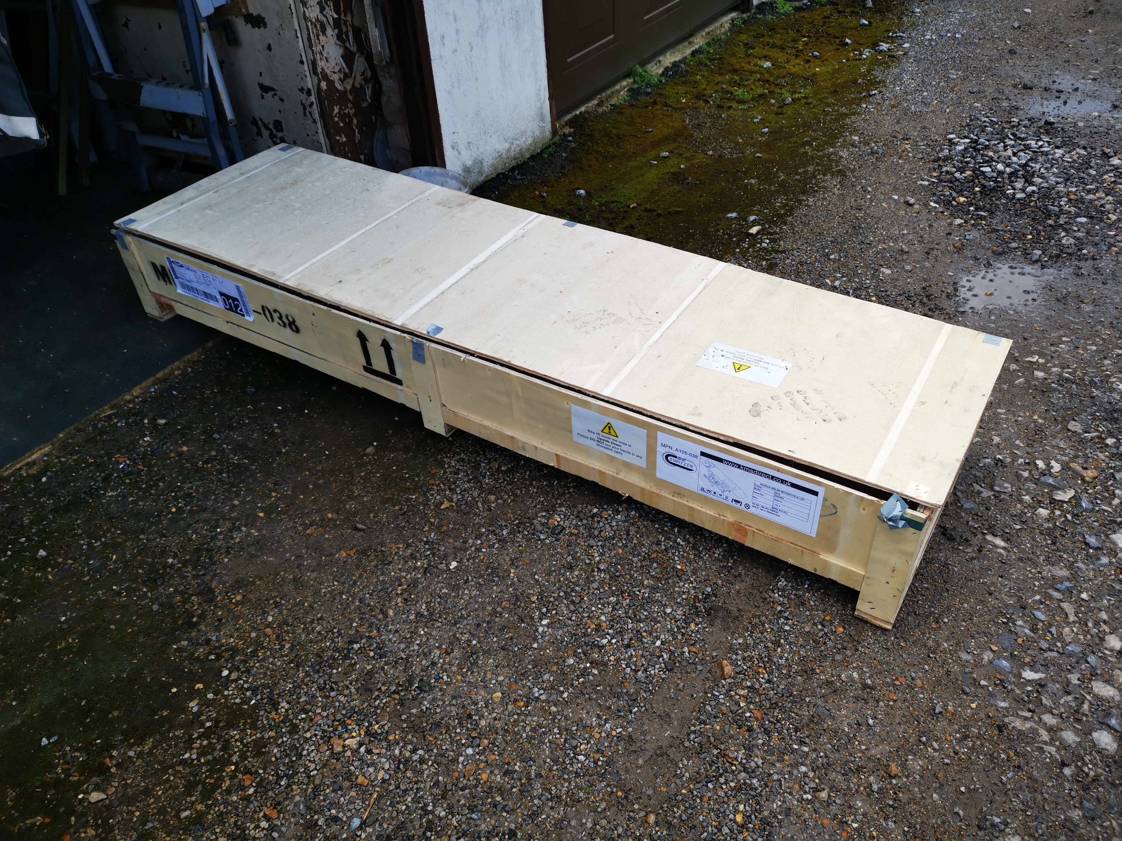
The lift arrived in a plywood box - 10 m thick, poor quality ply but I'll use it for something.


The ram is going to spend most of it's life extended - I've coated it with ACF50 to try and inhibit corrosion. The lifting pedal you see here is removable.


At the front end, there are two jacks that stabilise the lift and a stout bar that holds the lift in two positions should the hydraulics leak down.

I'm really pleased with it.

Almost a year later, after the lift had been in constant use I added a new wheel clamp:


It's much more rigid than the original one.


Saturday 20 April 2024

FH - Lucas HF1441 horn

While waiting for bits for the QR50, I took the opportunity to refinish the horn for the Huntmaster. It tests OK in that it pulls a current and deflects the diaphragm, so some adjustment will have it working.

Lucas catalogues are very useful. This is catalogue 716A, section F - six pages of horns and horn pushes. The application page tells you which part number you should have:


In the case of my 1958 Huntmaster, it's a HF1441 model horn, part number 70048. The spares list tells us a bit about it:


It's black, and looks like this:


So, I had the correct horn (bought from eBay I think - it was missing from the kit) and all I needed to do was strip it and give it a coat of paint.

First up was the various bits of bracket:

It’s good to clean the points in these horns, but this nut is usually very tight and it retains the diaphragm to around the moving point. I had it soaking in Plus-Gas for a few days but I couldn't shift it:


Since the horn worked I gave up and cleaned the old paint off with emery tape. 

I painted it with the usual U-Pol etch primer and gloss black. I know the tone disc is supposed to be black, as is the nut, but it looks nice like this: 


Friday 19 April 2024

FH - followers, pistons and barrels

 With the little QR50 out of the way and the FH back on the bench, we can get on with the build. The barrel has been painted for a while, the bottom end is in the bike, there's no primary or timing side and no pistons. Off we go:

First step is to fit a circlip to each piston; the gudgeon pins come out with some mild warming and are refitted just as easily. As you can see, I've put a large rag under the pistons as I don't want a circlip in the crankcase at this stage, and the pins go back in and the circlips go on without any drama.


Next, we can refit the reground cam followers. I've ground the radius back into these such that they now have no wear grooves. The retaining screws and pins (with the missing ball) have been refitted:


Next, we fit the ring compressors - these are just strips of tin held in place with ty-wraps. These were cut for the SQ4 and are not really long enough for these larger pistons. You'll see the wood - these are to prevent the pistons rocking about when the barrel goes on.


Before the wood strips go in, we squirt oil all over both small ends. 

The wood strips are wide enough to completely stabilise the pistons while we put the barrel on, but first we use Threebond 1215 to apply the base gasket to the barrel, to keep it out the way. This wasn't ideal as I was forever wiping gasket goo off my gloves -  it would have been better to have the gasket, goo down, on the crankcase and apply the goo to the upper side after the barrel was over the rings.


After a lot of fiddling, swearing and anguish the barrel went down. The compression rings were not too bad but the three piece oil control rings, with their thin 'rails' were a pain to get in as they popped out of the compressors before they were caught by the barrel.

They went in eventually, and we can retain the barrels with four nuts.