Monday 26 February 2018

Tecalemit Grease Guns

I've seen a few posts recently on Tecalemit grease guns which were often supplied in the toolkits of our bikes. People have problems with them, complaining that they don't work and consequently changing all the grease nipples to more modern types to work with modern snap on grease guns. There's no need for this - these guns work perfectly well if you know what you are doing...

Tecalemit type 7MC toolkit grease gun
There are several different types of grease nipple in the pages of history, but here's the type these guns are used for - The Tecalemit 'Tecazerk' nipple.


Here's one on the girder forks of my Ariel W/NG. Note the cylindrical shape with the rounded end & the tiny ball valve:


These guns are simple to use, but there are a couple of tricks you need to pay attention to to make them work - and keep working. The gun consists of a brass cylinder with spring loaded plunger - the end of the plunger is spun over into a machined recess in the cylinder, so it won't come off; the plunger is attached to the piston which pushes greases into a bore (A) in the cap. Grease is contained in the cylinder (B) above a cork seal. The nose of the gun is is retained into the cap using a fine thread and a hemi-spherical shape is formed in one end to accept the nipple.


Grease gun anatomy


To fill the gun, the end cap is removed and the volume B is packed with grease, pushing the cork seal down to the bottom of the cylinder. The trick here is to avoid leaving any air bubbles in the body of the gun. Do this with a straw inserted right to the bottom (before filling) and withdraw it carefully, filling as you go and by warming the grease before you start. You can pack the cap with grease before you put it on to prevent air bubbles forming in there too.

Filled with grease
To use the gun, start by cleaning the nipple and making sure you can see the tiny ball valve. You might have noticed there is a check valve in the grease gun and another one in the nipple - they are critical to the operation of the gun. If the ball is stuck and you operate the gun with no nipple on the end, you will get air in the gun and it will only work once. Place the gun over the nipple squarely - it helps to put a cotton rag between the nipple and the gun (old tee-shirts are good for this). This improves the seal between the gun and the nipple and the grease will happily go through the fabric. You can then push the plunger as many times as you want, keeping the gun aligned with the nipple.
Operating the gun
Here's how the gun refills itself. When you release the plunger, the springs close the ball valves and the piston, as it moves back, generates a small vacuum in volume A shown by the white space in the drawing.
Back stroke produces vacuum in Volume A
As the piston emerges from volume A, grease moves forward to fill the void, pulled forward by the vacuum. At the same time, the cork washer moves forward, effectively reducing the volume B until all the grease is used up.
Grease from volume B fills void in volume A

This demonstrates the criticality of the ball valves and the use of the cotton rag - the absence of either prevents formation of the vacuum in the cylinder, which prevents recharging of the gun. Without the vacuum, an air pocket will be left in the cylinder and volume A will not refill and the next stroke will not pump any grease out of the gun.

So the moral of the tale is, carefully fill your gun and take a rag with you in your toolbox!

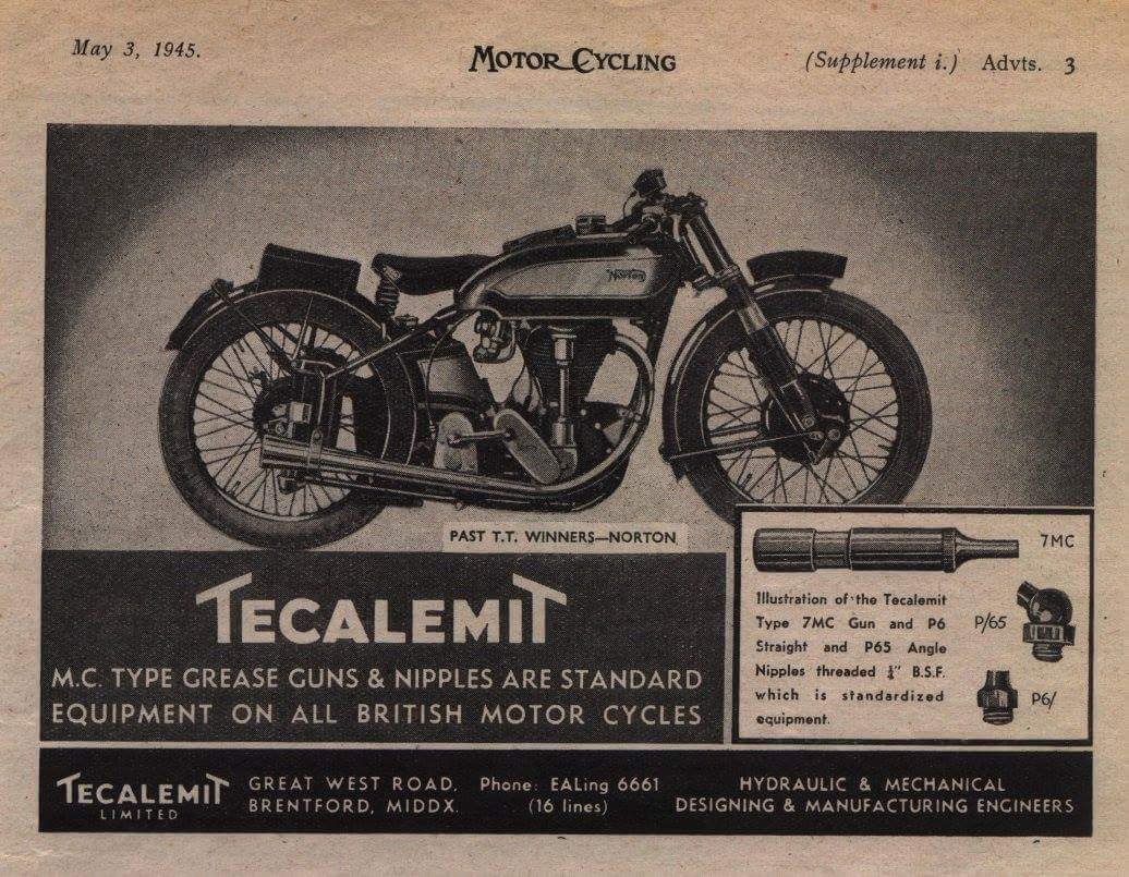
Lovely period advertisement - courtesy Richard Payne

Thursday 15 February 2018

Front Wheel Bearings - SQ4 Mk1

Here we have an Ariel front hub, with the half width brake. It's the one referred to by Draganfly as the 'Type 3' wheel. It's also the one that deposited that hub full of grease all over the first set of brake shoes I fitted to this bike...


So, this winter it is time for some new wheel bearings. The first job is to pop the cover off the bearing retainer with a large screwdriver:


The bearing retainer needs to be cleaned up and the gunge removed from the holes


This is the tool you use to remove the ring. Don't try and remove those soft brass rings without it...


Once the bearing retainers are out you can drift out the bearings and clean out all the old grease:


Ariel must have changed this hub once of twice, because the assembly described in the parts book and found in my hub does not match the illustration owners manual or in Mr. Waller's book. In my case, the brake side bearing rests on a 1/8" thick spacer in the hub, and has two 1/8" spacers attached to the ID of the bearing, one on each side. One is a top hat, and one a thick washer shown below. To replace the bearing you have to drift them apart, easily done in the vice with a socket:


The bearing is an RLS7 2RS, which is 2" OD, 7/8" ID and 9/16" thick with two soft seals. Easily obtainable on eBay


The non-brake side bearing is an RMS6 2RS which is 2" OD, 3/4" ID and 11/16" thick with two soft seals. It drifts straight into the hub with no extra spacers, followed by the brass bearing retaining ring which in this case was a bit mangled.


The new brake side bearing is easily reunited with its spacers, using another, slightly larger socket to rivet the two halves together again:


The 1/8" spacer goes in first:


Followed by the bearing assembly:


And the retaining ring, with its own retainer. the bearing retaining rings are not fitted with their seals, since these are not needed and seem to extrude into the space occupied by the spindle and the centre of the brake plate.


Job done. Time change the inner tube (it was a cheapo one which leaked slowly) and to refit the wheel.


SQ4 Front Brake

As part of winter maintenance, I have my front wheel off for new bearings, a new tube and a look at the brake. It appears that I still haven't got it right.

Take a look at this, it is the leading end of the trailing shoe:


To me, this is indicating that I haven't got the adjuster tight enough - there is about 20-30% contact on both shoes, at the cam end - in both shoes, there is no contact at the adjuster end. Here is the leading shoe, trailing end:

In both cases you can see where the lining is worn by contact with the drum. The brake is nothing like as effective as the one on my W/NG, which is obviously a much lighter bike but the brake has much more feel. They are bedding in at the cam end (trailing end of the trailing shoe here):


I'm happy to see that the drum is nice and clean, with no trace of grease


Less happy to see the heat damage to the paint, but we will deal with that when the weather warms up.

Setting the drum up with emery tape and double-sided sticky tape in the traditional way results in much better contact. By the way, don't do this with one of the wheel bearings missing since the spindle, and the brake plate and shoes will not be concentric with the drum:

Set the brake plate up such that it is pulled down to the bearing and is held rigid (as far as possible with these pressed steel brake plates) - that way the shoes will be as cylindrical as possible. I've used a short tube spanner on the spindle to take the place of the fork leg, and I am holding the brake plate from turning with a tommy bar. I turn the wheel to sand the linings.

Start with adjuster backed off and gradually wind it in, turning the wheel a few times and then dismantle again for inspection. When your satisfied that the adjuster end of the shoes is ground down enough to fit the drum, put a bit of pressure on the brake cam lever and repeat. Stop when you have contact over most or all of the shoe.


Here's the leading end of trailing shoe:


Leading end of leading shoe

 Lots of dust after the process is complete:

Saturday 3 February 2018

Headlamp Rims & Glasses

As part of the winter lighting upgrade I had to change the original, rusty BPF reflector to a H4 fit reflector to suit the new bulb; I bought this from Paul Goff and all was well, until I came to fit the rim to the shell and found a very tight fit - much worse than normal.

Pushing too hard, I cracked the new glass: £35 down the drain.


However, after the event I realised that I wasn't too happy with losing the old Lucas BPF glass, with the Lucas logo in the middle and that actually this was a blessing in disguise, though it might not enhance my beam pattern too well. I decided to replace the broken glass with the old one, that I would extract from the original rusty reflector.

I started with the spun edge of the reflector here:


And I introduced it to the bench grinder, removing the metal until I broke through the fold:


The spun edge of the rim could then be prised off and the old glass released. You can see the poor condition of the silvering:


The glass was in need of a clean, but otherwise came through the process unscathed:


The new reflector had the rest of the broken glass removed, by pushing the glass out with a metal bar through the bulb hole and by removing the edges with pliers. The glass is held in with a relatively soft mastic which you can cut easily, and if you are trying to remove a modern glass and keep it whole you can cut the mastic around the glass, and then lift the edge of the reflector off the glass at a small slot in the reflector (seen on the far side of the picture). You can get a small screwdriver in here and start the removal process:


I used a similar product to put the new glass back in:


Getting the rim on was still a challenge. I removed most of the new paint from the edge of the shell; made sure both the rim and shell were circular; fitted the rim without the lamp unit and checked clearances for the W clips around the rim.

It was not until someone suggested greasing the shell (thanks Les!) that it went on - a bit of silicone grease on the rim had it slipping on easily.