Friday 18 September 2020

W/NG - Assembling the bottom end

I said the next step was to sort out the camshaft, and it was. The reason for that was that I wanted to replace the camshaft bush in the timing side crankcase before the crankcase halves went together and I have done that, because I have found the camshaft and I know what diameter the journal is - I'm confident that the bush can go in as-is, and not need reaming.

So without further ado I can clean the bearing journals and use the Rothenburger MAPP torch to warm up the cases and drop the bearings in, with their spacer and circlip on the drive side.


The crankshaft has been away at Alpha Bearings in Dudley, the UK's premier supplier of big ends for classic motorcycles who have replaced the big end and realigned the crankshaft at what would have been a very good price (and with a one-week turnaround) had the small end eye not turned out to be oval. I was aware that it was very worn and for some reason had no oil hole. The crank came back from Alpha true to less than 0.001" and looking excellent:


The small end eye now has it's lubrication slot. I had a small worry when I thought the mainshaft was not correctly pressed in - though Alpha's had not touched the shafts:


I spoke to Alpha and several people in the club about this suspecting that I knew the answer - it is a taper fit. Alpha explained that if this gap were absent, you could not be sure the taper was pulled up correctly - so that's another one for the memory bank. The AOMCC audience all concurred, so I am happy again.

So next, we are into shimming the crankshaft for the prescribed 0.008-0.012" endfloat. This is the set up I used - the DTI is actually attached to a magnetic stand on the vice anvil, and the heavy crankcase assembly is just sitting on the bench. Not ideal, but I found that if I move the crankshaft against the case using a twisting motion with a screwdriver (flywheel to inner case wall), that cases will not move at all.

In this way, I found that I had a total of 1.4 mm endfloat with no shims. That's about 0.055".


That's a start, but we need the correct endfloat with the rod in the centre of the crankcases. To do that, I used a bore gauge to establish a position where the rod to crankcase measurement was equal on both sides and measured the end float from this position.


I have some 0.3 mm (0.012") and some 0.5 mm (0.020") shims, of 26 mm ID. Time for some calculations:


That leaves me with 0.22 mm end float, or 0.0086". Perfect.


I bolted up the crankcase halves sealing the joint with Threebond 1215 and assembled the cases into the frame, fixing the front engine plates loosely onto the crankcases and then dropping the lot into the frame, retaining it with the single 1/2" stud at the bottom of the down tube. 

When you start on the rear engine plates, you do the drive side first, with two studs into the engine and hold the plate to the frame on the gearbox top stud, then pass the footrest bar in. If you don't do it this way you will never get the spacer in.


When that is done you can put the rest of the bolts and studs in with the timing side plate and the magneto platform. If you look closely you will see the bash plate fitted, though you cannot finally bolt this in place if you have not put the sump plate on.


You can see why the magneto platform needs those extra studs and bolts to stop it flapping about.


I made an earth wire for the magneto:


With it all tightened up, I did some trials with the timing case. Turning the engine over with the camshaft, rockers and half time pinion in place sounded awful, so I had to investigate.


That pinion is knackered. I also realised that the camshaft bush that measured up OK was actually oval - I should have looked for that before. It was OK in one direction but when I looked at 90° to the original measurement I could see it was quite worn.

The next step is to pull the engine out again, replace the camshaft bush and reassemble with a new half time pinion.

Sunday 13 September 2020

W/NG - Preparing the bottom end

We're having a couple of days off from DIY, the railway and allotmenting and I've walked the boy so it's time for a bit of motorcycle activity. After putting another coat of black enamel on the Model A front mudguard and rear stand, I clean the bench down and pull the W/NGs cases out of the frame, where they were after the engine plate trial fit.

First job is to pull out the base studs and clean the gasket faces:


One of them is extremely stubborn and I elect to scrape around it. It's a bit more fiddly but we don't want to damage the stud or the case for the sake of making the gasket preparation a bit easier.

I've measured up the camshaft and the cam bushes in and found that the crankcase end camshaft journal is in poor shape - the wear is mostly in the camshaft. I'll seek advice on that one, but the crankcase end bush can come out when I pull out the old main bearings.

I use the excellent Rothenburger MAPP torch for this, with my infra red thermometer:


I heat the area around the bearings to 135°C, and this is enough to tap both bearings out in one operation:


The drive side has two bearings. One drops out quite easily at a similar temperature, along with it's spacer; the other is retained by a circlip:


This is a bit tricky, as son Thomas has my small circlip pliers but it comes out with the assistance of a scriber and a small screwdriver:


Next, we need to sort out the camshaft.

Sunday 6 September 2020

Model A - a stand, and a mudguard

A couple of new parts arrived for the Model A last month - a 5" D section mudguard blank - actually a rear, but cut down it will be perfect for the front:


It matches the original rear mudguard and is far more appropriate than the 1931-1949 mudguard it arrived with:


It's had a coat of black enamel. The plan is to let this harden, age and chip by leaving it around the workshop for a few years, then it will look the part:


I've also got a rear stand - an excellent reproduction from the Ariel Klub Slovakia. Apparently Slovakia was a strong market for Ariel before WW2, and there is a great following for Black Ariels there.

That's had a coat of black enamel as well:

W/NG - Magneto Platform Repairs

The AOMCC forum is a wonderful place to learn stuff about your bike. A while back, I fixed a broken lug on the W/NG timing case which supported the magneto platform; the magneto platform is a steel plate welded to the offside rear engine plate down it's centre line, so it needs support to resist the tension from the magneto chain.

You can see it here, roughly assembled to my crankcases:


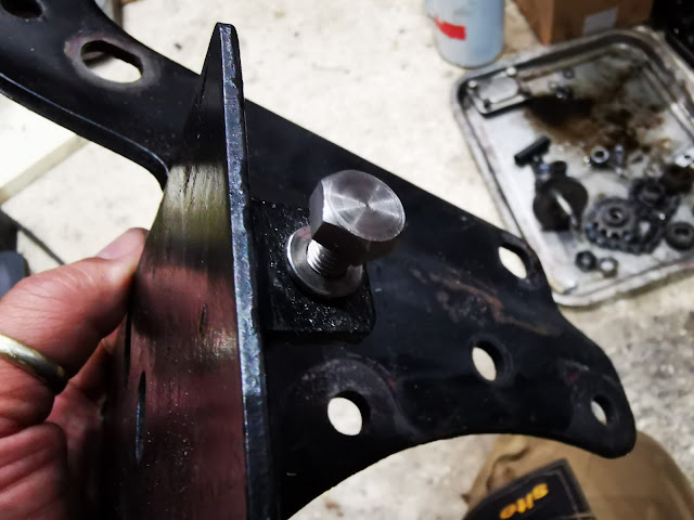
What I didn't realise, and what I learned from the forum is that the platform is supported at the other end as well, by a bolt through this hole - which was missing. I had a look through the hole, but as predicted by the forum members the lug into which the bolt screws was also missing - it's spot welded to the plate, so it probably wasn't a very meaty lug


You figured out that this picture shows the same assembly but upside down, right?

So, we have the engine apart so we will make a new one. This is a bit of scrap steel, about 4 mm thick and maybe 20 mm x 15 mm. I've marked a line down the middle where I want a tapped hole 1/4" x 26 CEI.


I've put the plate behind the hole, so that my marked line sits in the middle of the hole. I'll hold it here and scribe a line in the paint around it.


Using the scribed line, I dot punched the corners of my lug position before removing the paint with the Dremel. The dot punched holes let me see the position after attacking the surface with a sanding wheel. I'll clamp it in place with a toolmaker's clamp:


Then, we have a dose of TIG at 60 A. It's a thick bit of plate so it needs a lot of current - it also needs a lot of stick-out as it's a bit awkward to get the torch in.


Now, after cooling and cleaning up on the wheel we can repaint the plate. Then we have to assemble the plates into the frame with the crankcases:


With it all bolted up, we can mark the position of the tapped hole through the other plate using a scriber:


We can pull the plate off leaving most of the assembly still together, and we find a neatly marked hole which can be drilled and tapped:


Next, I need to remove the crankcases and put the main bearings in.