Monday, 28 March 2022

Charlie's Shed - Making a sidestand

 The sidestand fitted to Anstey-framed Ariels is a poor affair that does not extend very far from the frame and has a very small foot which combines to make the use of the stand a very precarious and risky operation. I never use it. 

However, the bike is a heavy old thing which would benefit from a decent sidestand so in this episode I'll show you how to make one.

I bought a leg, a while back, from eBay. It's from a Suzuki TS125 trail bike, so it is very long and it came with a spring and a M10 x 1.25 bolt. Doing this again, I'd probably buy a Triumph or Enfield leg as I ended up cutting a lot of length off this one.

The sidestand is going to bolt on, but I'm not a fan of clamp on types so this is going to bolt across the two bottom frame rails forward of the sump plate. A piece of steel bar, 6 mm x 35 mm spans the frame. I start by putting a 45° bend in a short length at one end, to start to get an idea of how it will look on the bike and what sort of leg length I will need, where it will sit in the 'up' position and where the stops will need to be. I drill a 10.5 mm hole for the bolt and fit the leg:


The first decision I make is that the spring will be underneath, not above the leg as Suzuki had it. I'll cut the peg off and smooth the area:


While the 6 x 35 mm flat bar can provide the 'down' stop, it needs extending to provide the 'up' stop. I make a piece with a double prep and weld it on:


Some shaping with hacksaw, files and the linisher gives us two stops:

The stand is going to be held on the frame rails with three 1/4" U bolts, one on the drive side and two on the timing side. Here's a trial fit of the first one:

With the assembly in place we can look at the leg length, and the angle it is going to make with the ground. Obviously if the stand's touch down point is further away from the bike's centreline, the bike is more stable. We don't want the stand leg too short, but leaving it like this won't allow the bike to lean enough.

Next, we need to stiffen that bar. It's stiff, but this is a heavy machine and we don't want a rider sitting on the bike while it is on the stand opening our stand bracket out. The stiffener is a piece of 20 x 3 mm flat bar


The stiffener also provides somewhere to mount the spring lugs. I made these from a bit of 10 mm round bar on the mini-lathe:


One of the key issues is to get the lugs in the right place such that the spring holds the leg firmly in both positions, without the spring fouling anything as it moves:

There was way too much slop between the stand leg and the mounting bar. I built up the bearing surface with weld and cut it back on the linisher to get it to about 7 mm

It's much less wobbly. Obviously wobble here will affect the lean of the bike when it's on the stand.

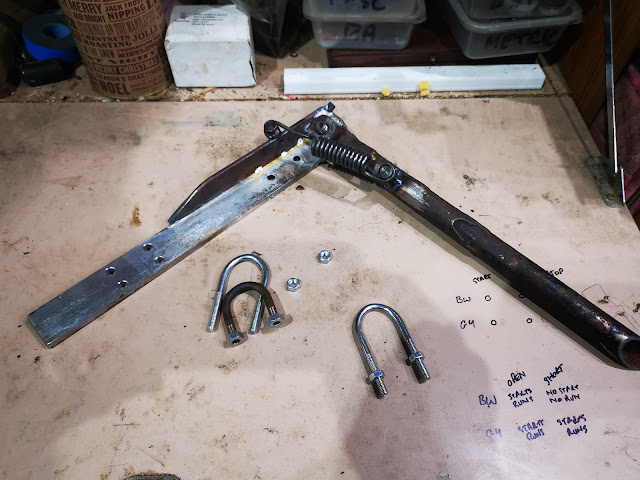
Time for another fitting. At the previous trial fit, I marked the position of the timing side U bolts, so now I can drill the holes. I haven't yet trimmed the mounting bracket, but I have trimmed the leg. Here are all the bits:


The bike has a lean of maybe 5°, which is fine.


Time to start finishing the leg. Here's the foot, cut from a bit of 3 mm sheet. The sheet happened to have a hole in it, I'll fill it up later:


Gosh that was quick. In this next picture, the foot is partially welded on and I have made the foot finder from some 10 mm round bar and another bit of 3 mm sheet. To start with, I fitted the stand to the bike in the up position and held a 200 mm length of the round bar in place, deciding where I wanted the foot finder - it needs to come out behind the foot rest and to do that I needed a bend. Once I had the bend formed I held the round bar on the foot with a spring clamp to see if it was in the right place, and I was able to see how long the bar needed to be and where on the foot it needed to be fixed. I tacked it on the foot.

Next I made a 25 mm square pedal, and curved it a little to emulate the shape of the brake pedal. I tacked that on the end of the bar and refitted the stand, which revealed various issues. These were resolved by removing the leg and holding it on the vice, heating the round bar to perform the bends I wanted - the bar curved around the exhaust, but not tightly enough, and the pedal was not square to the bike in two axes. A bit of heat soon fixed those issues. 

That's it for now. The stand is back in position and working:


I'll run around with it for a while and see how it goes. I still need to ease the 'u' bolt holes on the timing side and trim the end of the bracket before painting, but for now we need to shake it down.

Friday, 4 March 2022

FH Dry Build - Magneto Cutout Switch

There's lots of jobs to do on an old bike project - some dramatic, some messy, some tedious, some hardly noticeable. One of these is the magneto cutout, which is a small Lucas 76207 horn button mounted in a folded steel bracket to one of the handlebar clamp studs. It's here:

You'll recall I made some nuts last week - one of these was the locking nut for the cutout button:


The bracket will be a bit of 2 mm cold rolled sheet, but its a bit of an odd shape as it has to appear from under the top yoke, go forward under the handlebar and then pop out between the handlebar and the casquette. It took me three goes to get it right in cardboard:


I made the next prototype in 0.8 mm sheet which I could cut with snips and fold easily:


This looked OK but the switch wasn't quite in the right place:


It took me two more goes in this sheet before I felt confident that I wouldn't be wasting time if I went to the full thickness. Of course, at 2 mm thick it was going to need a bend allowance and it's straightforward to build that in during the marking out stage.


Here's a close up after drilling - you can see the double lines showing the position of the bends. I use a bend allowance equivalent to the thickness of the material - in this case adding 2.0 mm to each bend.


Here it is again, having been cut out with the hacksaw, filed and linished to the final shape:


I didn't take any pictures of the folding in the vice. I was careful to use the smooth jaws, have the bend line exactly aligned with the top of the jaws and to observe the bend forming as I pushed it over, such that the bend was formed between the two bend lines.


That's it. I've added it to the list of small bits to be zinc plated later.