Saturday 25 November 2023

FH - more shims & trimming nuts

 Following Thursday’s abortive first attempt, I pulled the cases apart again for a look at the big end nuts and to fit another shim to the drive side main bearing.

Roger Gwynn, all round guru, Ariel Hero and founder of Draganfly Motorcycles (without whom us Arielisti would be lost at sea) told me on the AOMCC Forum that the big end nut/crankcase clearance is close in these engines but you don't need to remove much material to avoid a clash. Roger recommended grinding some material from the cases.

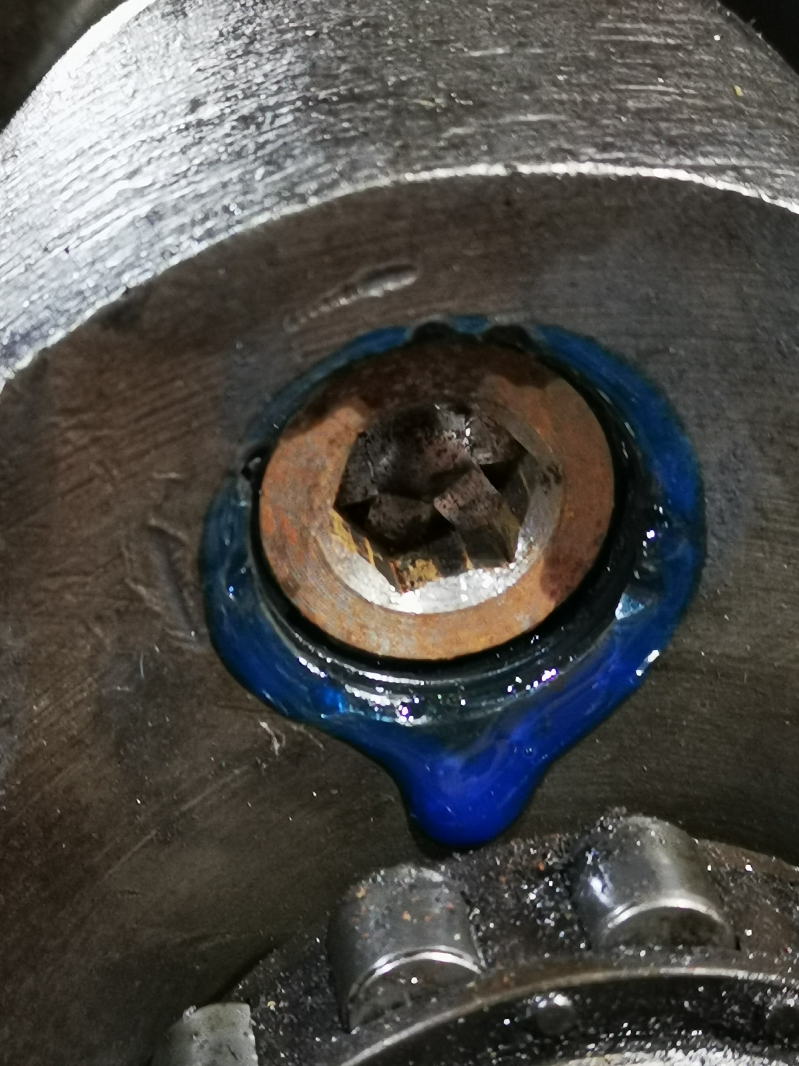
What I've done today is make a 1 mm chamfer on the offending edges of the two timing side nuts, so now I know what clearance I need to provide. If I can provide that clearance without modifying components I will be a happy bunny.


Club member Mick suggested that the fact that no bolt thread protruded beyond the nut wasn’t satisfactory, since the locking part of the nut was probably bearing on a reduced (tapered) part of the thread:

I've ordered a new set of nuts, still self locking but to a slightly shallower pattern (still big end nuts, not something nasty) and I'll use these with larger but thinner washers I think. That will guarantee the self locking bit of the nut is on the full diameter of the bolt thread. I’ll probably have to make the washers myself on the lathe.

Meanwhile, adding a 0.1 mm shim to the 0.25 mm shim already there has given me 0.07 mm end float, or about 0.0027”.

That will do nicely.

Thursday 23 November 2023

FH - Assembling the bottom end

 With the crankshaft together and the few internal components of the crankcase assembled, it's time to put them together. First step is to thinly coat the mating faces with Threebond 1215:

With the cases bolted together, we can measure the end float again. This time we have 0.18 mm - last time we had 0.34 mm, and I added one 0.25 mm shim under the bearing. Something has changed, or I have made an error because 0.34 - 0.25 = 0.09, not 0.19...

That's 0.0075" - we are aiming at 0.005". I'll see what shims I have in stock.


The next challenge comes when we check crankshaft rotation - it doesn't. There are two clashes one on the rear of the case, one on the front; the rear is a scrape that allows the crankshaft to move, but the clash at the front is more serious and prevents movement altogether. You can see the witness marks in the picture - this is probably the big end nuts fouling the crankcase:


That's coming apart again.

Tuesday 21 November 2023

Ariel Huntmaster vs. BSA A10

The purpose of this post is to look at the engine specifications, or the state of tune, for the various Huntmaster models and see how they compare with the closest BSA A10 models. We'll figure out which A10 is equivalent to the Huntmaster.


Here are the areas under consideration and the data I've found from reviewing the books:

Compression

  • 6.5:1 Golden Flash & Huntmasters 1954-1959 
  • 7.25:1 Optional for Huntmasters 1954-1959, standard for Cyclones
  • 8:1 Road Rocket, Optional for Cyclones
  • 8.3:1 Super Rocket
  • 9:1 Rocket Gold Star

Camshaft

  • 334 "standard" - fitted to the Golden Flash from 1950 - 1959 & Huntmasters 1954-1959 
  • 356 "sports" - Road Rocket, Super Rocket until 1959, Golden Flash from 1960 & Cyclone
  • 357 "race" - Super Flash, Spitfire Scrambler and Rocket Gold Star. Also fitted to the Super Rocket from 1960.
  • 358 "acceleration".

Valves

  • Inlet 1.406 Huntmaster 1954 -1959, Golden Flash 1950-1957, Super Flash / Rocket 1953-1960
  • Exhaust 1.375 Huntmaster 1954 -1959 Golden Flash 1950-1957
  • Exhaust 1.381 Super Flash / Rocket 1953-1960
No head changes for Cyclone

Carburettors

  • 76/276 (1 1/16" bore) - Rigid and plunger framed Golden Flash, also swinging arm Golden Flash & Huntmasters in 1954.
  • 10TT9 (1 1/16" bore) - Super Flash and Road Rocket, also Super Rocket until 1961.
  • 376 Monobloc (1 1/16" bore) - Golden Flash swinging arm frame, Huntmasters 1955 to 1959 and Spitfire Scrambler (1956 - 1959).
  • 389 Monobloc (1 1/8" bore) - Golden Flash 1960 on.
  • 389 Monobloc (1 5/32" bore) - Spitfire Scrambler (1960 on), Super Rocket (1962 on) and Rocket Gold Star.
No carburetter changes for Cyclone

Conclusion

So there you have it:
  • A standard Huntmaster is equivalent to a BSA Golden Flash, the most basic A10
  • A Cyclone is close to a BSA Road Rocket, though with a slightly lower compression ration unless it is fitted with the optional 8:1 pistons
  • My bike will be equivalent to a standard specification Ariel Cyclone.

FH - Finishing the crankshaft

In our last post, we determined that the big end clearances were good. At the same time, I checked the new gudgeon pins in the small ends and found those to be good too, so with the sludge trap cleaned and assembled some time ago we can commit to closing up the big ends with the proper big end nuts. These are £3 each, and can only be used once.

We torque them up to 22 lbf.ft, or about 29 Nm using the Draper 3/8" torque wrench.


I took the chance to clean the crankshaft down again with some brake & clutch cleaner and dropped it into the drive side crankcase half which I had laid out over the hole in my bench:


Here's another view, showing the new 356 camshaft as fitted to BSA A10 Road Rockets and early Super Rockets.


Tomorrow, I'll use some Threebond 1215 to seal the crankcase halves. Meanwhile, I need to sort out the bolts to hold the cases together. I have this lovely box of studs from Acme Stainless:


This sketch, from Draganfly's 'List 15' (a very useful document) shows where the studs go:


Friday 17 November 2023

FH - Plastiguage and the big ends

 Next step is to check the big end clearances. I've measured the journals, but I wanted to get some evidence of the clearance that I had ended up with after fitting new -0.030" shells. There isn't much detail on what the acceptable clearance is  before you must regrind, other than the data describing the sizes you regrind to and the recommendation that there should be minimal clearance after regrinding.

Waller indicates 0.003"- 0.004" for the big end shells used on 1948-1955 Square Fours (Fifth edition page 37); Phil Irving quotes 0.001-0.0015" clearance per inch of diameter (Tuning for Speed 3rd Edition), which equates to 0.00165 - 0.0025" for my 1.65" big end. Mr. Irving, otherwise known as 'Slide Rule' using those delightful pseudonyms beloved of motoring writers in the '40's, also notes that the clearance can be much larger as long as oil pressure is maintained.

So, let's introduce Plastiguage. This is a paste, extruded into rods a bit like Plasticene. You trap a bit in the bearing and squash it, so that the known Plastiguage rod diameter is squashed to take up the clearance of the bearing - you then use the card provided to determine the clearance from the width of the squashed Plastiguage. Plastiguage comes in different sizes to measure different clearance ranges.


So, you cut a length to suite the bearing like this, and then you make up the bearing. You make sure the bearing is clean first.


When you open the bearing again you can see the squashed Plastiguage and you can compare it to the card. This suggests something like 0.002 - 0.0025" clearance for the drive side. I'm happy with that.


This is the timing side, and it's about the same:


All good there then. Next job is to make sure the oil flows into the big ends. I'll inject it into the timing side oilway:


And it comes out the drive side big end!

During this process, I removed (with a little heat) one of the gudgeon pins from the new IMD 7.25:1 pistons I got from the AOMCC so I could check the fit in the connecting rod little end bearings. This proved to be perfect once I had cleared a small burr from one side of both bearings; not sure how that came to be there.

Happy days.

Tuesday 14 November 2023

FH - Crankshaft assembly

 Now we need to look at the crankshaft.

First up is the sludge trap. Keen readers will know that we cleaned this out some while ago, so all I have to do today is run a cloth through the hole to clear any dust and debris:


The sludge trap was cleaned at the same time, so we just give that a rub over with a cloth.


One of the flywheel bolts passes into the sludge trap - perhaps to stop it rotating. It's safely in place:


I'm using the hexagon type sludge trap plugs. This one locates the drive end of the sludge trap:


It's held in place with medium Loctite threadlock:


This is a terrible picture, but it serves to show the plug has successfully located the end of the sludge trap:


The plain timing side plug is also held in with Loctite medium threadlock.


Next, with the sludge trap closed up and the flywheel bolts done up tight, we can trial fit the connecting rods using ordinary nuts. We don't want to use the real nuts yet, since they cannot be reused.

Now, these big ends should be 1.657/1.6565" according to the BSA data sheet; this one measures 1.656/1.655", so we are 0.0005/0.002" undersize. I felt this was close enough and ordered the corresponding -0.030" shells from the twin spares man at the AOMCC.

The first trial assembly is now complete, and you can feel a small amount of play with dry big ends; this disappears when the bearings are oiled.

I've ordered some Plastiguage to determine what the clearance really is. 

More on this later.

Saturday 11 November 2023

FH - Sump

 This is a short post about a simple thing - hardly worth it you might think, but simple things sometimes trip us up.

I'm working up to building the bottom end, cleaning the crankcases, checking the oilways, things like that. I fitted the oil pickup pipe with a sealer called Permatex No.1, on the advice of some club members - it sets solid and that can be useful in some applications:


Here it is in place. You can also see one of the extended studs I fitted - the sump I am using is considerably thicker than standard. The studs are fitted with Loctite medium strength threadlock.


And another picture from underneath:


This is where it all goes a bit pear shaped. In the next picture you can see that the pickup pipe doesn't fit through the hole in the strainer - one of them is wrong, and this illustrates one of the pitfalls of building old bikes from bits. There is a question over which one is wrong, exacerbated by the knowledge that the strainers fitted to Huntmasters are not the same as those fitted to BSA A10s.

Now, we all know that 'the Huntmaster uses a BSA A10 engine', but actually surprisingly few parts are common. You would think, given that the crank and rods are the same and the crankcase is identical in some areas (not those relating to the timing chest, which is a different shape) that a simple thing like a sump strainer would be common too - in fact, wouldn't the canny design engineer use the bit that was already available in BSA stores? Well, no. And this my friends is perhaps indicative of why our laudable, innovative motorcycle industry went to the wall.

After contacting several experts, it transpires that the sump strainer is indeed different. Given that the strainer was manufactured by SRM (famous for BSA A10 parts) I thought perhaps I had been supplied the wrong one; apparently not. Draganfly Motorcycles, who I bought it from, actually modify the SRM A10 part into a part suitable for the Huntmaster by moving the hole.

We Ariel owners would be lost without them.


It turned out that the pickup pipe was bent - easily fixed when you know what you are aiming at.


With everything now fitting together, I decided to use Permatex again to seal the strainer to the sump plate, on the basis that the original pressed metal sump plate would have been sealed to the gauze strainer somehow as they were supplied under one part number and there is only one gasket listed in the parts book:


I greased the gasket on both sides as this is a service item and I would expect to remove it periodically.


All that remains then is to fit the sump plate. It's got a magnetic trap and this is deliberately oriented away from the pickup pipe to stop the magnet affecting the performance of the ball valve.


Monday 6 November 2023

Charlie’s Shed - Lucas U39 switch repairs

I’ve got a few Lucas U39 switches - in fact they are on most of the bikes. I have two on the bench at the moment, a civilian one from the FH and a military one destined for the W/NG, which has an extra position which illuminates the tail light only.

These notes are intended to record a few areas where these switches get damaged and to show ways they can be repaired. You’ll need a few simple tools and materials.


The first problem is the rotor - the part that fits in the knob is worn. It’s supposed to be a cylinder with two flats, but the flats are so worn & corroded that the knob wobbles about. What I’ve done here is make a fence around the shaft with sellotape and filled in the centre with JB Weld. It had previously been thoroughly cleaned with alcohol.


Here is a close up view of the finished rotor - I have used needle files to restore the shape of the flats fitting into the knob, being careful to ensure the pointer aligns with the text moulded into the top of the switch:


Next is a Bakelite repair, again with JB Weld. Someone has tried to prise the switch out of a panel with a screwdriver and broken the moulding in several places:


To fix these problems, the first thing to do is clean it all down with degreasers, brushes and scraping. I built a fence around the repair with some plastic card:


Removing the fence reveals hardened resin ready for shaping:


A short session with a flat file produces something we can paint:


Here we go. A little matt black U-Pol finished with a smear of silicone grease brings the Bakelite up nicely:


Next up, the contacts. Some of these switches have moving contacts operated by the rotor, which get corroded and full of muck. In this case, the spring had corroded away; to remove these contacts you have to withdraw a tiny split pin. I had to drill what remained of the split pin out with a 1 mm drill in a pin chuck. 


You can buy these torsion springs on eBay, but once you have made a few and perhaps have a few bits of piano wire lying around in various diameters it is easier to make your own.

The last job is to soak the brass parts in an ammonia based cleaner for a few hours. This removes all the tarnish:

Sunday 5 November 2023

FH - Ammeter rebuild

Way back in the dim & distant past, when I was still working, I rebuilt an ammeter for a friend and blogged it as ‘Tim’s Ammeter’. This is another one, a similar 0-8-0 amp CZU27 from the Huntmaster kit. It’s not in bad shape.


It’s a bit grubby and scratched as you might expect, so I will pull it apart for a clean. There isn’t much glue on this one and it comes apart easily.


All in bits with nothing broken:


Here’s a curiosity - it’s dated January 1960. It must have been replaced at some time, though it’s correct for 1958.


It cleans up nicely.


This is interesting. The power supply is set up for constant current:


These aren’t hugely accurate! This is actually at full scale deflection, but as you can see it’s only passing 7 amps.