
Thursday, 20 June 2013

Bond of Brothers

Hermetite... Hylomar... Yamabond... Wellseal... Hondabond... B&Q Bathroom sealant????

So many choices - but which one?

In the old days, in these situations I used to use traditional Red Hermetite or more recently Wellseal. I've also use blue Hylomar in the past. Usually the selection is made on the grounds of availability - what I had in the toolbox at the time.

I've no real engineering information for any of these products, and have never made a proper assessment of them.

However, for the SQ4 I wanted to look at a modern sealant. I hope to avoid tearing the engine down again anytime soon and with the legendary folk tales of excessive engine temperature (300 F at the plugs) I wanted to make sure I had something which was:
  • suitably rated for temperature 
  • compatible with engine oil 
  • compatible with aluminium 
  • a suitable colour (i.e. not red & smeared all over the cases!)
Several books and web forums I have read, both bike & car related (& even stationary engines!) mentioned Threebond products, Yamabond & Hondabond. Now, a quick Google reveals that Yamabond & Hondabond are both rebranded Threebond products.

Threebond describes itself as a fine chemical technology company with its roots in the automotive industry. Apparently, more than 90% of the world's motorcycles are assembled using Threebond products. Probably worth a look then!

Threebond say:

1200 Series silicone-based liquid gasket fills gaps on a flange surface and thus completely prevent leaks. When cured, it forms an excellent rubber-like elastic body offering excellent resistance to vibration and shock. Also it has an excellent resistance to heat, and effectively seals joints that are subjected to high temperature.

Here's the specification for Threebond 1207B:
  • Excellent chemical resistance against coolants and engine oil 
  • Outstanding mechanical and thermal resistance 
  • Excellent adhesion even to slightly contaminated surfaces 
  • Extremely fast curing 
  • Instantaneous impermeability for pressure- and fire test. 
  • Acceleration of the curing process by heat and contact with the medium 
  • No shrinkage and no generation of corrosive gases 
  • No corrosion of metal and only very slight reaction on plastics 
  • Normal disassembly
Here are the material properties:

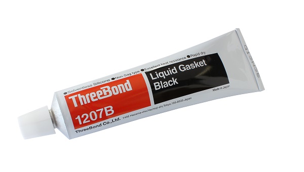
 I now have a tube of this. It has a Honda label & part number!


Tuesday, 18 June 2013

Bottom End Assembly

Thanks to the ever-helpful Brenton Roy, I have the torque figures for the connecting rods:


This is from the excellent AOMCC Knowledgebase.

Oil Selection

I read this article. And this article

And I decided...

To be continued!

Build Lubricant

One of the things I need to do in order to proceed with engine build is decide on what build lubricant to use. There are a number of things we ought to consider:
  • Different parts of the engine see different service parameters – e.g., the pistons & rings service temperature is very different to that of the main bearings
  • Loading is very different in different parts of the engine – e.g. the cams and tappets experience load through a sliding interface; the cam bearings load is experienced through rolling ball bearings with a much higher point load
  • Build lubricant ought to be selected according to the length of time between build and initial running – the lubricant needs to stay in place prior to star-up
  • Build lubricant ought to be selected according to the ambient conditions 
Casting around various personal & web sources, I came up with the following principles:
  • Pistons and rings need a special lubricant to avoid the lubricant clogging the honing marks on the cylinder walls and carbon deposits in the ring grooves. Something that burns away quickly is appropriate, like Two stroke oil or WD40
  • Consider pre-lubricating the engine prior to lighting up. This gets most of the crap from break in out because it has not had time to settle and is still suspended in the oil. 
  • Do not forget to pre-lube both ends of the pushrods too
  • Everything must be CLEAN or nothing will work properly. 
So, condensing all that experience down:
  • Engine oil for valve rockers, guides & stems 
  • WD40 for cylinders & rings 
  • Engine oil for crankshaft main & big end bearings 
  • Lithium grease for cams, tappets & pushrods 
  • Turn the engine over on a power drill prior to start up.  
  • Oil and filter are changed immediately after 20 minute initial run while engine is hot

Saturday, 15 June 2013

Just to assimilate thoughts on the bottom end...

An empty but patient crankcase
Not a very exciting blog post, but it will help me to figure out where I am on the engine rebuild...

So, the state of play this morning:
  1. The cases are fully machined, clean and partially polished.
  2. The connecting rods have new bushes and shells and have been polished. New nuts are available.
  3. The crankshafts are machined and cleaned, and I have the new oil way plugs available
  4. The camshaft has been machined & cleaned
  5. I have the coupling gear cover polished, the coupling gears and their seals & bearings ready and I have a new gasket and a set of studs and nuts from Acme Stainless. I also have a coupling gear 'pusher' to help me pull the crankshafts through the coupling gears.
Front crankshaft during stripdown
So I need to do these things next:
  1. Finish polishing the cases
  2. Assemble the crankshafts & connecting rods
  3. Assemble the crankshafts & camshaft into the cases
  4. Fit the bottom end into the bike
  5. Assemble the coupling gears and fit the cover - filling it with oil through the overflow hole
And I need to make these decisions:
  1. Decide what building lubricant to use
  2. Decide how to torque up the big end nuts
  3. Decide what sealant I am going to use on the crankcases
  4. Decide what oil I am going to use
I'm sure there is more...

Wednesday, 12 June 2013

Starting on the engine!

Well, summer's here and the bike is coming together. I've finished my welding work, the wheels are still away, and most importantly I have some time away from work to get to grips with things at home.

So, in a break from repainting the kitchen we will start work on the bottom end.
 
I'm dithering around polishing the crankcases which is a noisy & messy job & which stops me rebuilding the engine. Someone also suggested that polish would hinder cooling - but equally it is obvious that the engine was once polished - it is deeply tarnished now, but you can see it is still very smooth - you can also where it wasn't polished!


But, I have all the parts and can get moving with the rods & cranks.
 
You'll recall from previous posts that the rods have been cleaned and polished and have spent the winter protected by some pipe insulation in their own box. I have small end bushes and big end shells from Drags along with new big end nuts, also from Drags.
 
These are shown in the adjacent picture and will have to be pressed into place and reamed to the finished size.

 
The sizes are shown in the table below and are around 11/16" - but will have to be sized to fit the factory specification using a suitable adjustable reamer. In this case we will use a 21/32" - 23/32" reamer, which are readily available but are of highly variable quality. Beg, steal or borrow a decent one if you can! If you must buy an internet cheapie, take a look at a few things before you use it and if it is no good, send it back!

Take the reamer to pieces. Measure the length of each blade, and make sure they are equal.
  1. Look at the retaining nuts, make sure they are not too loose and clean the threads
  2. Clean out the grooves in the reamer body and make sure the blades can sit snuggly down in the grooves. You don't want any swarf in there.
  3. Put the reamer back together, and measure the diameter across two opposite cutting edges (this only works on six blade reamers) at each end of the blade. The dimensions should be the same! They are not supposed to be tapered. Repeat the operation for the two other pairs of blades.
So, to fit the bushes. You can use a press for this, if you have access to one, but a bench vice comes a close second. You could also use the draw-bolt method, but I suggest the loads are probably too high for that approach. These bushes are quite tight.

  1. Find a socket or a piece of tube which is small enough to support the small end eye, but large enough, both in length and internal diameter, to receive the old bush.
  2. Open the vice enough to receive the rod, the socket and the new bush plus a couple of millimeters.
  3. Find a piece of soft sheet (brass for example) to protect the end of the new bush.
  4. Align the socket, the rod eye and the bush. You might benefit by putting a short rod of about 1/2" OD inside the assembly, just until you have the new bush a couple of millimeters into the rod, just to keep things lined up.
  5. Nip the whole lot up in the vice with your protective sheet on the jaw pressing on the new bush.
  6. Operate the vice to push in the new bush, pushing the old one out into the socket. You will probably find the initial force required is much higher - and you might get a bit of a bang as the bush starts to move. This is normal. Don't be afraid to apply a bit of heat to the small end eye to get it moving - but go easy, this is aluminium. No Oxy-acetylene here!
  7. Carry on pushing until the new bush is more or less flush with the face of the rod. My bushes are about 0.5 mm over length at the moment.

The next job is to drill the oil hole. Do this before reaming and you don't need to worry about deburring later. The Square Four has 3/16" holes in the small end eye.

Next - reaming to size. Get ready with your gudgeon pin, your internal micrometer or bore gauge & a 1" micrometer.
 
Now, adjustable reamers are really scraping devices. They are designed to scrape out small quantities of metal from holes and as you have seen (from when you inspected your new reamer) they are not as rigid as solid reamers and can only be used to take small cuts.

When you set the reamer up for the first cut, back off the adjustment collars (i.e. screw them away from the square end of the reamer) to reduce the diameter of the reamer until you can put the reamer into the bush. Now adjust it larger until it just begins to touch the inside of the bush. Turn it using a tap wrench a couple of times with some oil.

Be careful to twist the reamer such that it is concentric with the bush; make sure the blades pass right through the bush. That way you will minimise the potential to cut a tapered hole.

You want to increase the size of the hole in very small steps, testing with the gudgeon pin at each stage -  DON'T SKIMP ON THE CHECKING!! Small end bushes are relatively cheap, but replacing them repetitively is tiresome. Increase the size of the cut by turning the collars by 1/8 of a turn each time, and turning the reamer in the hole 3 or 4 times. Always make sure that the top collar is tightened down.


A few more thoughts:
  • NEVER turn the reamer BACKWARDS – can You could break or chip a blade.
  • Never put more than ¼ turn on the collars
  • If the reamer jams, loosen the blades and pull the reamer out and start again. Remember a jam will leave a number of ridges and these have to be cut away or it will happen again.
  • Make certain that the collars are tight.
  • Clean the reamer after each pass.
  • Do not push down on the reamer too hard or it will jam. Take it slow and easy - this is supposed to be a hobby remember? You don't need to hurry, you are enjoying yourself right?
  • On each turn try to stop in a different place.
  • Use oodles of cutting oil.
So, now we have our reconditioned connecting rod:


So, repeat the operation for the other rods and you will end up with a little heap of scrap like this:

So here is a table showing the dimensions I have ended up with:

Small End Bush
Big End
Factory Specification
0.6868”
0.6863”

0.003" wear allowable
1.375” min (journal)
Cylinder 1
0.686”
1.3765”
Cylinder 2
0.6869”
1.3745”
Cylinder 3
0.6863”
1.377”
Cylinder 4
0.686”
1.3775”

I had to order a couple more bushes from Drag's since I wasn't happy with No. 2 & No. 3. The table above shows the new dimensions.

And now, over the last couple of days I have polished the cases. I made sure that I polished only the areas that were polished in the factory all those years ago:

Next stop, bottom end assembly!

Tuesday, 11 June 2013

Oseberg Viking Ship

I’ve been in and out of Norway almost weekly just lately – it’s a beautiful country, though it does rain a lot.


Recently we were in Tonsberg, and outside the hotel along the quayside we met a lady who showed us around a boatyard where volunteers were building replica Viking ships using original techniques & tools – no saws, only axes, chisels etc. They had a forge on site where they were making rivets & nails… She spent about an hour walking us around the site one evening – it was fabulous – right up my street.


Friday, 7 June 2013

Biker Chicks...


A friend from Houston, Texas sent me this picture this week. An interesting shot from the 1920's presumably from Holland.

Is this an Ariel publicity shot perhaps? the bikes are both from 1929 I think, one a side valve and one overhead valve, both new touring models?

And look at their faces - noses, smiles - are they related? Mother & daughter perhaps?

Saturday, 1 June 2013

Pussy Galore

Since the summer is here, it is time to take the Bantam to Sheringham for the annual Classic Car & Bike Show.

This is a Sheringham Carnival event organised by the The Lobster pub and every year the town centre is closed off and filled with old cars & bikes for a sunny Sunday at the beginning of June. From The Lobster website:

Our previous three shows were a massive success with over 200 cars attending each year, and each year it has grown; from a 1929 Austin Swallow to a Ferrari 308 GTS. So whether an enthusiast, owner or just on a family day out, a great day is to be had by all.

The main high street and sea front will be closed for the day in order to best display the vehicles. We can accommodate larger groups as well as individual cars and last year had representations from Bentley, Ferrari, Porsche and members of the North Norfolk Classic Vehicle Club. Also on display were MG, Mini, Jaguar, Rover, Triumph Stag, Trojan and Austin A7.

Promoted and organised by the Lobster Pub and raising money for the Sheringham Carnival, the aim of the weekend is to involve people who live and work here, helping foster a real sense of community and fun. Hopefully benefiting local businesses by attracting more visitors who will have such a great time they’ll want to come again and tell all their friends too!

It will be a truly enjoyable event for all ages. Our programme is hoping to include music, dancing, a real ale festival and of course the classic car and bike show.


It's on Sunday 9th June this year, and when the time comes I'll post some pictures. It's a great little show, and followed six weeks or so later by a Harley Owners Group meet, when 400 or so Hogs fill the town - and if you don't go for the bikes, go to the Lobster. It's a great pub and you can take your dog!
Nice Shooting Star at the 2012 Sheringham Classic Car & Bike Show

However, having taken the Bantam up this weekend, I was pottering around town when I stumbled across a couple of lost Panthers, lost in the back streets of Sheringham.

These friendly chaps were on a ride out from their rally meet in North Elmham, Naturally I took a few pictures:

Friendly Panthers on a rather too cool June morning...

More Panthers & nice Goldie

Nice to meet you guys!

Thursday, 30 May 2013

Managing

I use this spreadsheet to manage my parts, track what I need, what I've ordered, what I paid or budgeted for the rebuild...

The parts are grouped by work package; can be filtered or grouped by vendor, order status, part number, or whatever you want.

Very useful. Here it is: http://pisl.co.uk//ArielAccounts.xlsx.zip

Thursday, 23 May 2013

Resting my weary feet...

Working around the oil tank & oil lines, I need to be sure that everything in that congested area is in before I can say I've completed work for Phase 1.

Fitting the footrest mounts in place, it is clear we have a few problems though they are easily fixed. These type of issues demonstrate clearly why a mechanical - only rebuild is necessary on a bike which is in pieces.

Take a look at the picture of the RH footrest hanger - it is clearly pointing to the rear of the bike and has perhaps unsurprisingly been bent at some time.

The left hand hanger, the one that passes through the primary case is nice and straight (it is a new pattern part) but unfortunately the anti-rotation lug on the engine plate does not fit in the cut out machined for it - easily fixed with a file, but not something you would want to find when it is just back from the powder-coater. And remember the Bantam fork legs - powder coat, if that is what you are going to use, is very thick and we will need extra clearance adding for the thickness of the paint.

Here's that footrest in a better place, after a session with the Rothenberger. We also have a clutch lever boot, making it's first appearance on the blog.

Easy job - grasp the end in the vice using the handy bolt hole, and heat the area you want to move to cherry red. Use a stout tube, Stillson, ring spanner or whatever suits your purpose and you can heave it back into place - don't hit it, bend it gradually using all your He-Man (Master of the Universe) strength and if you have it hot enough it will move easily and in a controlled fashion.

Let it cool, trial fit, go through the process again if necessary.

Oh and by the way - the other valuable lesson I learned was that no, the footrest rod spacer won't go in if the engine is in. One for the future, that one.


Sunday, 12 May 2013

Oil Strainer

As I said in my previous post, I still have welding to do but it is time now for something quiet. 

This is the oil strainer banjo bolt out of the bottom of the oil tank. You will note that the strainer is conspicuous by its absence - only a scrap of solder remains:


A strainer is a simple affair made from brass mesh - I selected some from an eBay shop at 40 wires/inch to be suitable for filtering bricks, flies and sweet wrappers from the cold viscous oil in the tank.

Strainers are easy to make. Select a former to match the diameter of the banjo bolt - I used a piece of chromed tube intended for making clothes rails. Pass it through the hole in the tank, and measure the maximum length of the strainer. Subtract the length of the banjo bolt.

Cut a piece of gauze to that length with your snips, or use scissors. You need good quality snips - scissors are fine. Loose or worn snips will just allow the wire to slip between the shear blades. Cut the width to wrap around your former and add 3/8".


Fold up 3/16" or so at each edge, shown in the photograph above. One edge must go up, the other down, as shown in the first sketch below. Wrap the gauze around the former so the edges overlap, shown in the middle diagram.


Ease the folded edges over one another with your fingers, so they lock together like the last diagram.

At this point, check the strainer fits over the solder area on the banjo bolt. If it's OK, find a suitable mandrel (I used a cold chisel) that will fit inside and press the seam tightly together with something hard & smooth (like the shank of a screwdriver)


Now you need to make the end. Cut a disc of gauze, about 3/16" larger than the former you used to wrap the gauze. Lay the disc over the end of the former, and press it into something soft - your palm will do. This will raise the edges of the gauze around the former. You can finish that off with your fingers. The aim is to make a little 'dish' of gauze.


When you've finished, set it upside down in the strainer (raised edges upward):


This is how it looks all together:


Next step, solder it up. Start by taking the strainer off the banjo bolt again. Use a small torch to heat the large banjo bolt, with some Baker's Fluid in the solder recess at the top. Tin this area with solder when it is up to temperature. Use ordinary plumber's or electrician's solder for this job, there is no point in using anything stronger.

When this is complete & cool, mount the strainer back on the banjo bolt. Use a big electric iron and some more Baker's Fluid to reheat the solder at the top of the banjo bolt and it should flow happily into the gauze. Now, after the bolt has cooled move the banjo bolt in the vice so that the strainer is horizontal and the seam is uppermost. Take your soldering iron and run a small amount of solder right along the seam. 

When it is cool again, have a look inside the strainer and make sure it is clean. This area is for CLEAN oil and goes direct to the oil pump - you DON'T want any gobbets of loose solder in there!

Fit the end cap, and dunk it in some flux. Use the soldering iron to run a small amount of solder around the end cap, fixing it to the barrel of the strainer.

Let it cool, and wash the flux off.

And this is the finished article:


On with the Oil Tank

Looking back, I realise that pulling those dents out cold was never going to work. The last time I did something like that, I welded the pins in and pulled the dents out hot.

Ho hum. With cracks like this, there was no going back:


So now you are all going to find out what the oil tanks looks like inside...

I decided to do what I should have done all along. Using the trusty hacksaw, I cut down each side of the damaged area. Using a cut off wheel in the Dremel, I cut a short slot, long enough to allow a hacksaw blade to pass through, in the long edges of the damaged area. Then I used a hacksaw blade to remove the damaged area:


The tank is made of 18 SWG sheet. So, taking a piece of cardboard, I cut a template roughly the same size as the hole and attached a loop of masking tape to it. I folded the edge of the card to allow it to fold around the edge of the tank. I then suspended this in the hole and drew around the inside of the hole, onto the card. I now had a card model of the repair patch I would need.

The shape was then transferred to a piece of cold rolled 20 swg sheet, and cut out with the Wiss aviation snips. I folded the edge in the vice, and then used some scrap material to press the joddle into both edges, so that the pieces would sit flush with the original surface:


I've shown it here, held in place with magnets. At this point it is important to dress the edges of the tank, take out any wobbles or dents and make sure that patch sits flat. This is not good enough:


All adjusted; and the butt joints at the short sides have been given a 45 degree weld prep. The panel is tacked in place with the MIG:


Fully welded. a bit messy in places, but I blame the lighting. The lights in my shop are either behind me when I am welding (so I am welding in the dark, with the lights shielded by my body), or if I switch the overhead lights on the sensor in my helmet picks up the brightness and darkens the lens - welding in the dark again:


Dressed with the flap wheel:


There was another weld/dress step as I tested the tank. I filled the tank with water (after it had cooled) and found several holes; these were welded & dressed; I now have two very minor holes left, but the family are complaining about the noise the grinder is making so I had better stop.

Sharpie rings mark the holes!

A couple of days later in a marvellous week at home - I have not travelled anywhere and I have the luxury of a wonderful wife who brings me Martinis in the evening - I'm done with the oil tank. It has taken two more leak test/re-weld/grind cycles to get the tank water tight, but now the repair is invisible as the day the tank was made.

A temporary coat of black hammerite, until we are ready for Phase 2, and we are finished.

Monday, 6 May 2013

Shrinking & pulling

After the gearbox was back in, I decided to have a bit of an interlude and sort out some of the fabrication jobs that had been knocking about.

Finding myself with a spare hour or two one day, I made a start on the dent in the oil tank. The tank has had a major league ding in it for some time. Some was on the AOMCC forum suggested it may have been a battery explosion - it looks more like someone has used it for target practice.

Taking inspiration from a good book 'Building Budget Brits' I decided to use a method involving brazing & pulling to remove the myriad of dents in the tank. Some of them were very deep & localised, clearly with a lot of stretching going on. Now I could have filled or lead loaded this tank and avoided all the work, but I'm keen to learn and try new things....

So the idea is, we pull the dent out without holing or cutting the tank by fixing a suitable stud, wire, piece of scrap to the bottom of the dent and pulling it outward. I'd hoped to be able to weld to the tank and to pull the dents out with the tank hot, much like I repaired the breather tower. However, I was a bit concerned that I might just end up holing the tank, weakening the area around the weld and pulling or tearing the material.

So I elected to braze plain steel nails into the bottoms of the dents and pull them out cold. This would be OK, because during multiple brazing operations the material would be annealed several times. Then, I put a steel bar across the panel being worked on, to act as a fulcrum for the pulling operation. I used a pair of combination pliers to grip the nail and pull the dent out.

So here is the first pass


Nails resited, here we go for the second time..

and a third attempt

and again - four times now...
So before the fourth attempt, we had created several 'peaks' to go with the considerable troughs already in the tank. Levelling the peaks gave us an opportunity to lose some of the stretched material, by locall heating (bright red) in the area of the peak and reducing the height with some light hammer blows.

This is almost at a stage where we could use some filler... Lead maybe...

But, reasoning that this was going well and I could get more of that dent out, I pushed on with a fifth go at shrinking & pulling. This was lower but more level until i cleaned the flux off and I realised the 50 year old steel had cried 'enough'! Take a close look at the picture and you'll see a lot of cracks have appeared:

I think that this is due to hardening. Of course, annealing or normalising steel has a time element to permit removal of stress and changes in the grain structure and of course cooling this thin material happens very quickly. Added to that, the material was obviously thin from 50 years of corrosion.

Max was very concerned:


Monday, 15 April 2013

Wheels


Sample spokes
Amid engine machining and gearbox rebuilds, I decided it would be good to actually ride Amelia at some stage. Standing in the way of this was a set of very rusty spokes on both wheels. I'd hoped to get away with commissioning the bike on it's own wheels, without any form of rebuild (continuing my 'Phase 1' rebuild with no chroming or painting) but it was not to be. Both wheels had at least one broken spoke, and the remaining spokes were very thin in places.
So, a rebuild it had to be.

Amelia has half-width cast iron hubs, front and rear. The front is the 'Qualcast' half width hub fitted to all telescopic-fork Ariels prior to the appearance of the full-width alloy hub in 1956, and the rear is the 5-stud QD hub. Tyres are 3.25-19 front on a WM2 rim & 4.00-18 rear on a WM3 rim.

Max has found some tyres
So, gathering parts. I used Central Wheel Services for spokes & tyres, since they give outstanding service and their prices for tyres were very good. I bought traditional Avon Speedmaster & SM MkII tyres, still made today in a modern soft compound.

Close inspection of the spokes revealed plain spokes on both sides of the wheel at the front, with butted spokes on the drive side at the rear, plain on the other side. This matches the description in the parts book perfectly. However, it didn't match the records at Central Wheel, so I had to provide sample spokes for them to manufacture against. I chose stainless spokes and plated brass nipples this time, since I was not at all happy with the nickel plated steel nipples I bought for the Bantam which, 2 years on, are rusty.

The first thing you must do when rebuilding a wheel is to remove the old tyre. Don't think about using an old tyre for a second - even if it has tread and sound sidewalls, the rubber will be hard as nails and will have you sliding down the road. 

Interesting paint under the original rim tape
Removing tough old tyres can be a challenge, and I often dispense with the traditional levers in favour of a set of bolt cutters, which I use to cut the wires in the bead. On an older tyre, I'll cut the rubber with a Stanley knife to ease the passage of the bolt cutter. Don't bother trying this technique with a modern tyre though, there's wire everywhere!
Rear rim offset
Next, find yourself a nice stiff flat board. A piece of 3/4" ply would be good. We need to measure and record the offset of the rim to some datum on the original wheel - the brake drum is very convenient. Place the brake drum face down on the board, and measure the distance from the edge of the rim to the board

Amelia's front wheel offset is 1 1/4" to the rim on the brake side;

On the rear, it is 9/16" to the rim on the brake side. On the rear, the offset is measured with the brake drum removed.

The next step is to photograph the spoke patterns. Make sure you have pictures of which spokes overlay others, which holes the go into on the rim and please also look at the dimpling on the rim holes and makes sure you know which way round the rim goes. 

Those of you who have read my Bantam pages will know I have rebuilt at least one wheel with the rim the wrong way round - the result is not pretty as all the spokes will be bent.

My reference photos are shown further down the page.

The next step is a real turning point in the rebuild: take your best bolt cutter, and cut the all the spokes. Do it within an inch or two of the hub. If you cut near the rim, it will be much more laborious to feed all the rusty spokes through the dirt encrusted holes on the hub.

Bolt cutters - did I really do that?
The next step is to get the rims off to the platers. This takes a while, so don't hang about! While they are gone you can clean up the hubs, get them painted, recondition the brake plates and replace the bearings.

Incidentally, I spoke to Tony at JD Wyatt Contract Polishing, who told me that it would reduce the cost of the polishing if I were to leave the painted rim centres in the blasted condition. Since this would provide a key for the paint, this is what I decided to do.

Spoke Patterns

Spoke patterns for the rear wheel:


Spoke patterns for the front wheel: