Work on the engine has stalled for a moment whilst we wait for FW Thornton to see if they can help out with a ring problem. The bench is now clear, so we can start on one of those other 'waiting in the wings' jobs that we use to fill in when the main workface stops for some reason. Bike building is like that - there is always something else you can do to fill in when waiting for parts.
And so to building the wheels. The 'jig' I use is just a piece of 19 mm ply that used to be part of a desk. The cutaway sections make it really easy to get to the nipples. It has a hole on the middle for the wheel spindle, which is a piece of 1/2" round bar. Using the spindle as a centre, I mark the outer diameter of the rim on the board. Using the offset measurements I made from the wheel earlier (
before I stripped it) I make up four wooden blocks to lift the rim off the board to the correct offset. The brake drum, which I use as the datum, is placed face down on the board.
And that is it. There is a much more sophisticated version of this idea in Frank Farrington's excellent book
'The Vintage Motorcyclists Workshop' which includes blocks to control the concentricity of rim & hub - I don't go this far, since when rebuilding a wheel from an intact but rusty version I can buy spokes to exactly the right length and I find that I get very good concentricity by virtue of that spoke length.
So here we go. Set the hub up on the jig:
Add the blocks to establish the rim at the correct offset:
Start adding spokes according to your
lacing pattern. You did photograph these wheels before you cut them apart didn't you? It helps if you lift the hub above the jig at this stage, so that you can insert the spokes from both sides. As you add the spokes, try to lay them out according to the lacing pattern. Start with half of the spokes on the lower flange, placing them in alternate holes, pointing in the anticlockwise direction (in the Ariel's case, these spokes have the nipples on the outside of the hub). Then, add the other spokes on the lower flange, pointing them clockwise and crossing the anticlockwise spokes according to the lacing pattern (in Amelia's case, these spokes are threaded from the inside out, have the heads on the inside of the hub, and cross under the anticlockwise spokes).
Then you move on to the spokes in the upper flange, again starting with the anticlockwise spokes. When you have finished, you will have this nice little nest of wire:
Next, lower the hub back on to the jig and lay the rim over the top. Look carefully at your reference photographs, paying close attention to the location of the holes in the dimples in the rim, and make sure you get the rim the right way up. You can easily assemble the whole wheel with the rim upside down, and not notice until you are snugging down the last of the nipples. I know -
I have done it!

Now, again we must be careful and work to a pattern, but a slightly different pattern this time. We don't want to scratch that shiny new paint! Starting again with the spokes in the lower flange, and your handy
lacing pattern, locate the dimple nearest the valve hole that corresponds with an anticlockwise spoke on the lower flange. Insert one of those spokes in that hole and screw a nipple on a couple of turns. Then, moving clockwise round the rim, insert all the anticlockwise spokes in the lower flange. Then, start on the anticlockwise spokes on the upper flange and continue until you have a nipple on all the upper & lower anticlockwise spokes.
The reason for doing it this way is twofold:
Working on spokes that point in the same direction means that the wheel is very flexible, and you can rotate the rim to get the spokes in the holes without endangering the paint.
Working on the upper and lower spokes in the same direction means that you cannot 'trap' the unfitted clockwise spokes whilst you fit the anticlockwise spokes. Because the clockwise spoke crossings are inside the anticlockwise spokes, they can't get stuck behind spokes that are already fitted.
Keep the nipples really loose to maintain flexibility - you are only trying to establish the lacing pattern and get the spokes in the right holes at the moment.
Next, fit the spokes pointing clockwise. Start at the from the valve hole, and fit the first spoke from the lower flange, followed by the first spoke from the upper flange. Moving clockwise around the rim, fit the spokes in turn - lower, upper, lower, upper - until you have all the nipples fitted.
Now, take the wheel off the jig and have a good look at it. Give it a shake. Make sure all those spokes are entering those holes easily - there should be no tension anywhere at this point. If you are happy, put the wheel on the jig and wind the nipples in until there are 3 threads showing, and repeat the look/shake process. You will probably need to use a screwdriver now, as the wheel will stiffen up.

Now, with the wheel back on the jig, wind the nipples in until there is no thread showing. As you do, make sure the spoke heads are seating properly in their countersinks. Look & shake again. Next step, run all the nipples down until the end of the spoke is level with the bottom of the screwdriver slot in the nipple; then go around again until the end of each spoke is level with the very end of the nipple - you will need a spanner or a spoke key this time. Off the jig again, you should find you have a very stiff wheel. If one or two of the spokes are still loose, snug them down now, as evenly as possible.
This gentle step by step approach to spoke fitting ensures that the wheel comes off the jig needing very little trueing up.
So next, trueing up.
Hopefully, having built the wheels on the jig, we will have very little truing to do. However, there is usually some runout, but the offset is probably good. By the way, the offset I measure from Amelia's original wheels was:
- Rear 9/16" on the brake side
- Front 1 1/4" on the brake side
Now, what is runout? There are two types of runout - lateral runout and radial runout, as illustrated by this handy picture I made:
Radial run out is, pretty obviously, an eccentricity of the rim relative to the hub. Lateral runout is when the axis of the rim is not parallel to the axis of the hub. Easier to explain with the pictures!
So, how to fix it? Well, you can do miracles with a spoke key, but first you have to figure out what is wrong. To establish this, you need to set the wheels up in a jig, like this:
This is made from two pieces of timber, glued and screwed to a cross member, held in the vice. There is a V-notch in each piece for the wheel spindle to rest in. At the bottom, adjacent to the rim, are two pins:
One is set up so it almost touches the side of the rim; the other so it almost touches the outermost edge of the rim. Spin the wheel in the jig, and you will be probably be able to see both lateral and radial runout. Move the wheel slowly, and you will be able to quantify the run out in both directions - it is essential to mark the rim where the runout is worst.
You'll want to get the runout down to 1 mm, or 1/32", in both radial & lateral directions. You've probably got about 3 mm or 1/8" now, right?
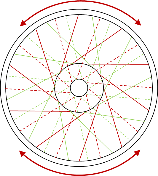
So the key to tackling runout is the proper adjustment of the spokes. Here's another of Simes' handy diagrams:
Ain't that pretty! A few words about it:
The dotted lines show the spokes on the non-brake side
The solid lines show spokes on the brake side
The 'upper half' and 'lower half' relate to positions on the wheel relative to a mark you will make on the rim during the truing process
The green spokes go ant-clockwise
The red spokes go clockwise
Tackle the radial runout first. Roll the wheel in the jig again, and relative to your pointer, mark the rim where it has most runout, i.e. where it is lowest against the pointer, where the distance from the outside of the rim to the centre of the axle is greatest.
Roll the rim until that marked point is at the bottom, and now you will have spokes in the lower half and spokes in the upper half. Because we have the worst runout at the bottom, the spokes in the lower half need to be shorter, and the spokes in the upper half need to be longer, to reduce the runout and make the rim concentric with the hub.
So, you must appreciate that the spokes which are more or less horizontal, and radiate from the extreme left and right of the hub don't have any effect on the runout. Conversely, those running vertically are controlling the runout and it is these that will be adjusted most. Those that run diagonally from the hub have more or less effect depending upon how vertical or horizontal they are.
So, using this diagram:
We can see that the spokes within the red arrows have more effect on the runout than those that are outside the arrows. To correct the runout, hold the wheel in the same position (with your mark at the bottom) and loosen the spokes within the red arrow at the top by, say, 1/4 turn. Loosen ALL the spokes within the arrow - the red, green, dotted and solid ones. Then tighten the ones at the bottom, within the arrow, by the same amounts.
When you have finished, measure the runout again. It should have reduced a little. Now repeat the process until you are satisfied that you have minimised the runout.
Correcting lateral runout is a little more complicated. Remember:
So again, locate the point where the runout is worst, and mark it. In this case, 'worst' means the point where the BOTTOM of the rim is furthest to the RIGHT, like the diagram above.
To tackle this lateral runout, adjust the spokes in this sequence:
- Loosen the SOLID spokes in the lower half of the wheel by 1/4 turn
- Loosen the DOTTED spokes in the upper half of the wheel by 1/4 turn
- Tighten the DOTTED spokes in the lower half of the wheel by 1/4 turn
- Tighten the SOLID spokes in the upper half of the wheel by 1/4 turn
Here is the diagram again to remind you:
When you have finished, measure the runout again. It should have reduced a little. Now repeat the process until you are satisfied that you have minimised the runout.
And that, ladies and gentlemen, is that. All that remains is to file off the protruding spoke heads:
File them flush with the nipple, so there is no danger of them popping a neat hole in your inner tube. Fit a nice new rim tape, put the tyre on and go and have a beer in the garden.



QE9s3HD)lkBR,U-L)O5g~~60_58.jpg)