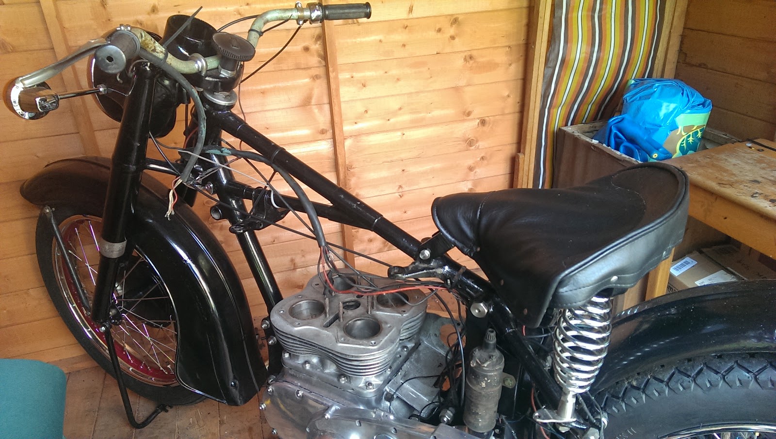
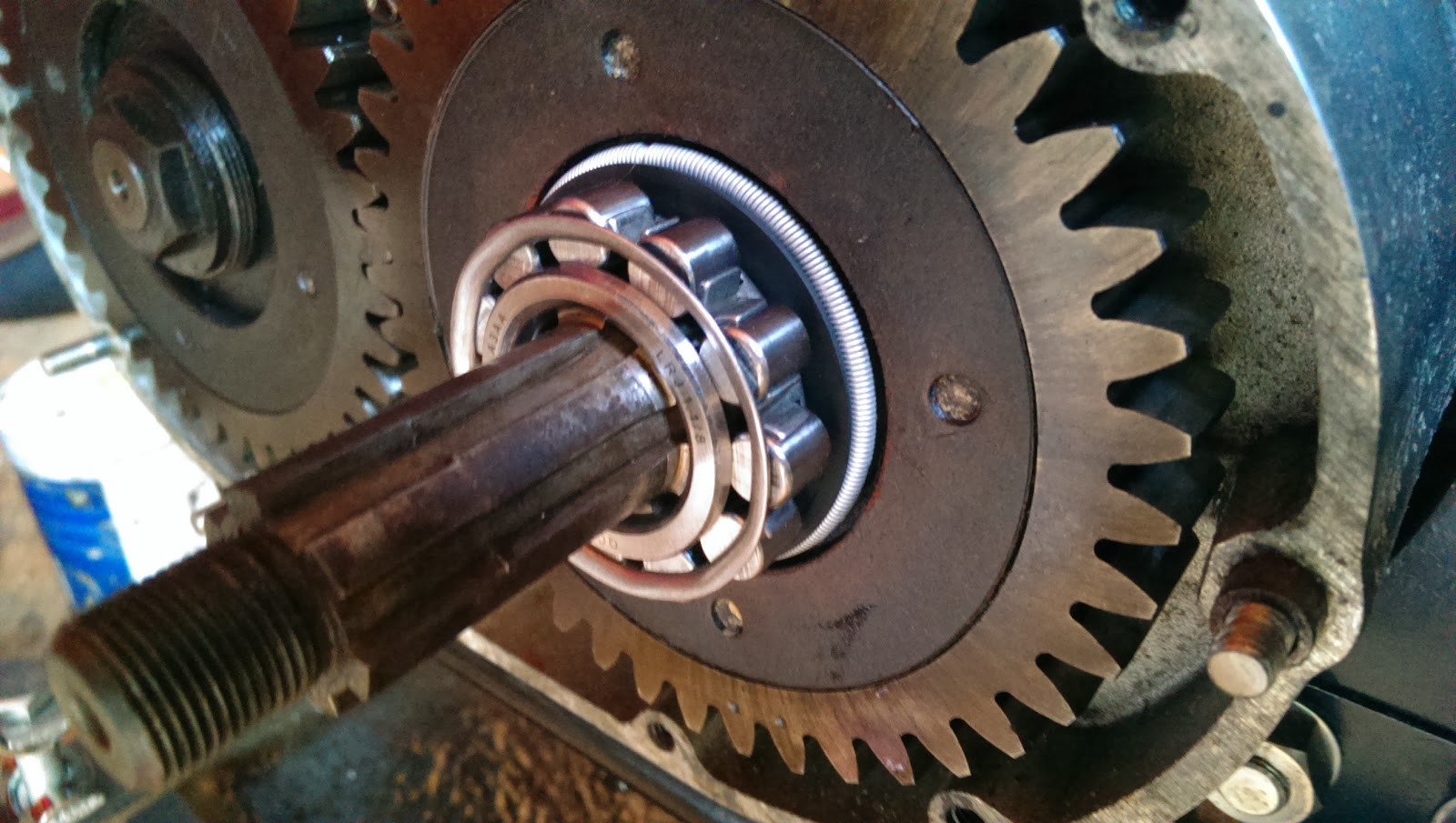
Tuesday, 22 April 2014

Cylinder Head Assembly

So, I have most of the parts to replace the head, apart from the high temperature sealant recommended by Bruce Longman. Over the past couple of days I have fitted the new head studs:


The thread into the head on later engines is 3/8" BSW, and there is a parallel section on the stud which has to engage with a counterbore in the head. You can see these here:


As the head had been skimmed, much of the counterbore had been machined away. To deal with this, I recut all the head stud threads and remachined the counterbore. Hours later, I have all the head studs in place. After I'd done all this work I ran the 5/16" CEI die down the eight studs in the block, just to make sure there would be no trouble when the head went on.

Next up was the polishing. It's fairly clear from the state of the casting that the fin edges, the 'V' along the top of the exhaust ports, and possibly the sides of the rocker box were polished - maybe also the carburetter flange. Personally I'm not sure that Ariel would have done this, since the rocker box sides would be quite difficult to polish without resorting to small buffs and hand work - there is no access for a polishing wheel, so this would have been time consuming & expensive. I've polished the fins for now; I also like the contrast between the polished rocker covers and the unpolished rocker boxes.


Final thing is the assembly of the rockers themselves. These are all back in, with a couple of replacement shafts (thread damage). One of these went in and out several times - and turned out to be too large on the OD, and with the two grooves for the 'U' washer in the wrong place. The best of the old ones went back in and the replacement will go back to the supplier.

So, now I am waiting for the high temperature sealant and the head can go on!


Sunday, 20 April 2014

Compression Ratio

I know the head has been skimmed, so I measured the combustion chamber volume with a graduated syringe. It measures 38 cc. Adding 6.63 cc for a head gasket nominally 2 mm thick and 2.7 cc for the dish in the piston gives me a combustion chamber volume of 47.33 cc, and a compression ratio of 6.26:1, quite an increase on the 6:1 stock figure.

Wednesday, 16 April 2014

Wiring Up

While waiting for head studs, I have the tank off, some spare time and some wire...

I can make the wiring harness. I have the old harness, which conveniently shows me how the various branches broke out of the rubber tubing to go under the tank and off to the dip switch, horn push and other places. It also shows me how it was constructed:


So, having fitted the old harness back on the bike, we can construct the new one around it.


I'm using rubber covered wire, as was originally used, obtained from a solar-panel supplier. It's a lot less shiny than the PVC coated wire we get now, but I'm not wholly satisfied - it is not as black as the original wire. I'll use some cheap tie wraps to keep it bundled together until I am ready to put the sleeving on:


You might recall that I made a wiring diagram, and we will use that to build up the new harness. I start by fitting some of the components so that I can lay in enough wire to reach them, like the dynamo and the ignition switch.


Then we lay in the wires, one by one, using loose tie wraps along the frame, handlebars and mudguard stays:


I'm using clear spiral wrap to hold the harness together for now, until I have finished laying it all out. I know from experience that it's better to work with this temporary arrangement until you have all the wires in and marked. There is always something to add or re-route, or lengthen!

These little uninsulated bootlace ferrules are very useful for tidying up areas like the ignition switch, horn and lighting switch, where the terminal is designed to clamp bare wire:

Sunday, 6 April 2014

Two heads are better than one

Regular readers might remember that I was lucky enough to find a reconditioned head at Draganfly a year or so ago, and wrote about it here.
 
Here it is again, ready for the head studs to be transfered to it from the old head, so that it can be fitted this week:
 
 
 Good plan, flawed by the condition of the old studs:
 
Worn threads


Worn & distorted threads

A bent stud
 
So, back to Acme for more studs... and nuts... and money...
 
And guess what? It wasn't until I wrote this blog post that I noticed that my 'new' head has a chunk out of the bottom fin at the back...

Tuesday, 1 April 2014

Small steps...

Just a little bit more. Front brake cable finished, fitted & adjusted. adjuster from Acme Stainless, boot from Draganfly, cable parts from VWP.

Saturday, 22 March 2014

More Goodies from Draganfly

This week, I have been mostly working... and shopping, getting ready for the top end rebuild. a few more parts from Drags and Acme, for the Square (and one, a secret one, for the Huntmaster). Otto head gaskets, rocker oil pipes, rocker oil pipe banjo bolt newly available from Acme, and the rocker cover locating pins lost during bead blasting.


And some more


And this, for the future - this is the strainer for the FH, recently available from Clay at Acme Stainless.


And a blast from the past:


The railway straight at Brooklands. Wonderful, magical place, right next to my office.

Tuesday, 4 March 2014

Fairly quiet on the Ariel front...

I have this old thing in my shed - as you can see it is an MZ TS250/1, as shown on one of the blog pages. I have been tinkering with it to try and make space for an Ariel...

But there is not much happening on the Square at the moment. Amelia now has her clutch cable fitted and the clutch lifts nicely - it is surprising light, but then I do not have the springs fully tightened up yet. The cable will need some lubrication - we msutn't forget that.

I've also fitted up the front brake cable - Length is good, but the adjuster block needed a little easing to get the cable in the slot. Soldering next time.


The next big job is to get ready for the cyclinder head. I will need:
  • head gaskets
  • a carburetter stud
  • one of the locating pins for the rocker cover
  • some time
Hopefully I will get to that within the next week or two, but there is business travel on the horizon...

Friday, 21 February 2014

Clutch

Having got the brake shoes back, I want to finish off a couple of cables that are cluttering up the workshop, before starting on the cylinder head. One of those is the clutch cable, and I would like to do a dry run of the clutch build. It's a dry run, beacause I want to spin the engine on the power drill using the crankshaft shock absorber nut, and I don't have the oil pump or any of the timing gear ready yet - because the head is not fitted.

So today I will fit the clutch temporarily, to have a look. First up is the basket, fitted over the cage & needle rollers. It's retained with new bolts and lock washer I bought from John Budgen.

Next up is the stack of plates and the clutch centre, preceeded by the final thrust washer. First problem appears - the new clutch centre nut is not happy on the gearbox mainshaft thread - though the old one still fits. This is the whole point of a dry build!
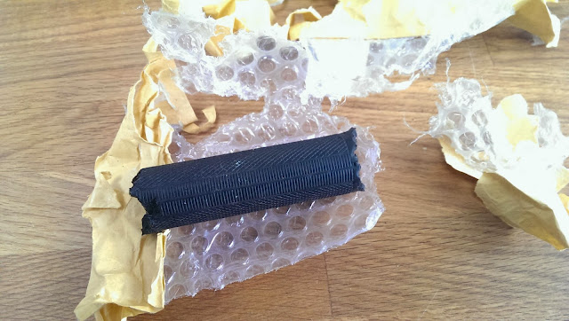
Push rod fitted!

The pressure plate comes next, followed by the cups, springs and the nuts. And the first outing for the clutch spring screwdriver I made a couple of years ago. Works fine!


The clutch operates very nicely using the arm on the other end of the gearbox, and the pushrod adjuster is screwed almost right in. Odd I think, the plates are in good shape but not wholly unworn. Most of them came from John Mitchell of the AOMCC. Maybe the pushrod is too short or there is a ball missing? The ball is certainly present in the adjuster cup...

Thursday, 13 February 2014

Brakes

Since I'm working on small fill-in jobs at the moment, due to a lack of spare time, I have been tidying up the control cables and making new ones. Before I fit the chain and chainguards, I need to sort out the rear brake as well. So it makes sense for me to visit the guys at Charles Johnson Bus & Truck Parts to get the brakes re-lined with a suitable modern material. This will enable me to finish & fit the front brake cable, finish the rear brake rod, fit the chain and top chain guard and sort out the bracket on the lower chain guard (which comes off a single I think - not a Square Four at any rate).

Brake shoe linings are made from soft and tough heat resistant materials mixed with compounds such as iron, brass, ceramic, and graphite. The lining can be either riveted or glued to the shoe. The lining has to create the maximum friction force from the meagre load you provide to the shoe using your hand on the lever, or the much greater load you can create using a modern hydraulic system. These materials have replaced the asbestos linings that were used with great effect until the ‘80’s, but which were shown to cause pleural and peritoneal mesothelioma, forms of cancer in people handling braking components regularly.

It’s almost inevitable that an old bike has asbestos brake linings. This is a hazard – particularly in the powdered form you meet inside an old brake drum. NEVER breathe brake dust. Assume that every brake system you are working with is hazardous and dispose of any brake dust properly.

Of course, like anything else in life, not all brake linings are created equal. A lining may be relatively soft, which will be quick to bed in and which would give medium to high friction forces relative to the load applied to the shoe. They would be suitable for normal road use, but would wear out quickly.

Or, you could specify a tougher material for heavier duty road use and touring which might also be suitable for some competition applications. This might last longer, but would need more force from the lever or hydraulics.

These days, most brake lining material is glued to the brake shoe using an adhesive designed to operate in the aggressive temperature to which the lining is subject. The lining is useful until the brake has run out of adjustment or has become ineffective.

Linings can be riveted to the shoe if required, and this is the traditional way. The disadvantage of riveted linings is that the rivet heads nestle part-way through the lining, meaning that the lining which is available for braking is much less thick and will require replacement sooner than a bonded lining.

So there we go. In a week or so, Amelia will have a new set of soft modern shoes. A few years ago, I was proud to be told by Danny (my MOT tester) that the brakes fitted to my 60 year old Bantam were better than those fitted most of the modern scooters he had in his shop.


So a week later I have my new shoes, with Ferodo 3921 lining material bonded to the original shoes. They are a much better fit in the drum, and although I have only tried them by hand, feel much more 'sticky'.


Monday, 20 January 2014

Primary Drive

The next step is to fit up the primary case for the second time. First off, make sure all the engine bolts behind the case are good and tight.


Then, a dose of Threebond on the flange between the two halves of the case, and bolt them up. This immediately reveals that we are missing three bolts - we have the nice stainless screw in the top, that came from Acme, but I have not sourced the others. So we can get on, one comes from stock - it's the right bolt, but the wrong material.


The clutch sprocket bearing cage goes in next, well greased and followed by the twelve needle rollers, courtesty of John Budgen:


Then the chainwheel goes on:


A quick spin reveals a horrible grinding noise... But I know what that is - I've forgotten the ring behind the chainwheel. Primary chain goes on, courtesy of Draganfly, with the clip safely fitted in the right direction:


I found that the primary chain is much easier to adjust if you flip up the rear mudguard - the access to the adjuster is much better.


So, all done. I need a few parts:
  • bolts for the two halves of the rear case
  • the bolt for the lower chainguard to the rear primary case
  • a spacer for the rear case to the frame
  • a split pin for the shock absorber
  • spring washers for the clutch dome screws.
But that's it for the moment. Here it is, all together:


Finish off the Coupling Gear Case

Well, lets get on. Inspired by a post in the AOMCC forum, I am going to fill the coupling gear case with engine oil prior to startup. The coupling gear case is filled by oil draining from a shelf in the crankcase, through a small tube above the gears. This mean it fills using oil splashed from the big ends, so would naturally take a while to fill after starting. I placed this small pvc tube into the drain hole - it passes out of the engine throught the sump plate which is not fitted at the moment:


When the case is bolted up, i'll fill it with oil and then remove the tube. Before we proceed though, does the exhaust bracket bolt fit now or after the cover is on? Best test it. Is this the right bracket for this side? There are two different lengths: 


Next the crankshaft outrigger bearing, held in place with Loctite 603. This is the one that is supposed to be 1 thou smaller on the inner race ID.


Coupling gear cover, new gasket and Threebond:


And all in place. Amelia is now on a drip:


I must remember to fit the spilt pin in that shock absorber nut. One thing I may have to correct later is that the two studs fitted at the 9 o'clock and 3 o'clock positions, the ones that pass through the dowels, are really about 3/16" too short.

The head is just sitting on there - it is the old original one and is not staying...

Saturday, 18 January 2014

Sunday, 5 January 2014

Reciprocating Engine

At last we have a reciprocating engine again.
 

Yesterday, pistons prepped with tinplate/tiewrap compressors, block ready with new gasket stuck in place with Threebond.


It took 6 hours over two days to get to this point. I'd get the block over all the compression rings, and it would persistently get stuck on number 1. After five attempts, which included checking ring radial thickness again, I realized that the 2nd ring on No. 1 had no shiny filed surface on the end - it was straight out of the box and had not been gapped at all.

That's what comes from working sporadically over several weeks. You need military precision on your record keeping, and to meticulously check & recheck what you did yesterday...


Here we have it all bolted down, with Threebond oozing out & Clay Jones shiny stainless steel nuts holding it all together.
 
Magic.

Saturday, 4 January 2014

Todays progress...

One pic today - and you'd have to have eagle eyes to spot what I have done!


Circlips fitted, small ends lubed up with engine oil, cams lubed ready for the block to go on.

I've also stripped the primary case off (& helicoiled a couple of holes), ordered the chains from Draganfly, cleaned out the battery carrier threads (which were full of paint), and tidied up the shed a bit.

Next stop, ring compressors. As it happens, 8-9 hours after writing the foregoing words this morning, I did do a bit more today. I finished my tin-strip ring compressors and did a trial fit of the barrel (well, it would have been THE fit of the barrel, had I not found that for some reason Number 1 piston will not slide gracefully into its cylinder, likes its brothers have done). The compressors work brilliantly though:
 

Base gasket in place ready for tomorrow:


Thursday, 2 January 2014

Before I forget again...

This sprocket has 25 teeth. Standard solo is 24; 23 for sidecar:

 
This one has 44 teeth; you can get a 40 tooth version as well:


And this one has 19 teeth hidden under the chain. This is standard:


The rear brake drum should have 47 teeth.

Tomorrow I need to order the chains.

A monumental day

Pistons in, rings properly fitted!