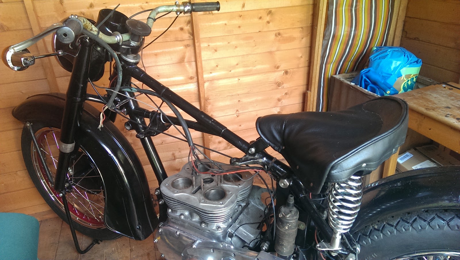
Wednesday, 21 May 2014

Diversions

En-route to Norway this week, I read Noel Whittall's 'A Stupid Thing to Do':


An amusing and inspiring read. Thanks Noel!

Norway is as beautiful as ever:

Akerhus Fortress

Aker Brygge, from Akerhus

Akerhus again

Trial Fitting Ancilliaries

Dynamo drops in OK. New gasket, greased one side, Threebond the other:


Trial fitting the carburettor. I'm concerned where the second fuel tap will go, and I quite see why it would have been deleted. Since I have no crossover pipe I am not sure what to do here.


Later that day I witnessed a man turning into a Sousaphone...


Orkestra del Sol at the Norfolk & Norwich Festival!

Monday, 19 May 2014

Exhausts... Left or right, big or small?

So I have these lovely pipes from Feked... But which way round do they go? I also have the square head bolts and their brackets from Acme, and they just make the puzzle worse:

Timing side. Small kink?
Or big kink?
Drive side. Big kink?
Or small kink?
With the small kink on the drive side the pipe appears to sit inside the brake pedal and prop stand more neatly, and the big kink on the timing side allows the pipe to sit inside the swing of the kickstart. 

Is that right?

The head is on!

So we are all set. The sun is shining, I have a day free (after cutting the grass and making the family dinner) and I have all the parts, plus a very nice text from Bruce Longman via Draganfly with explicit instructions. Max is in bed, so he will be happy for a bit:


A Chocolate Sprocker, feeling very 'Sunday Morningish'
I have some high temperature silicone gasket as recommended by Bruce. Loctite say this is suitable for operating temperatures up to 275 degrees C (sustained) with excursions to 300 C:


So as recommended by Bruce, we start by laying a band of sealant around the pushrod tunnels, on both sides of the gasket. Actually easier to lay one bead on the gasket, and one bead on the block, making sure you have the handed gaskets the right way around:


No picture, but next I placed all the head nuts in position between the cylinder block fins, under their holes, with the flanges upward. Next, manoeuvre the head under the frame tube and drop it into place over the studs, making sure the extended, rounded ends of the studs drop into the nuts. Add the sleeve nuts inside the rocker boxes, and the 5/16" CEI reduced hex nuts outside the rocker boxes. You hand screw these down finger tight.

And as Kees Knegt pointed out in a comment to an earlier post, this would have been easier without the rockers! You cannot fit the pushrods with the rockers in place either (they don't slide sideways far enough) so I may as well have left them off... although I do like to trial fit everything at least once.

Next, with your thinnest 5/16" CEI open spanner, engage all the nuts on the downward facing head studs and turn them as far as they will go without using and force. You will realise now that if you leave one undone, and tighten the others, you will crack a fin by virtue of the loose nut pushing downward onto the fin below.

Once you have all the nuts finger tight you will see the head finally come down onto the gaskets. continue going around all the nuts inside & outside the rocker boxes until they are all snugged down finger tight.


You will need a variety of spanners to achieve this. The reduced hex nuts in the middle of the head, under the inlet tract are particularly inaccessible.


So, when everything is snugged down, use Bruce's torque figures and sequence to tighten down the head.

Job done.

Friday, 16 May 2014

Huntmaster Rises up

The start of a build, in my book, is the frame & centre stand. The stand is essential to give the frame a stable start in life.

It was a bit worn:


Not a good picture, i wish I had taken a better one. I added some 16 SWG steel sheet, and a dose of this:


And some of this:


And now I have a couple of these:


Wednesday, 14 May 2014

More bits...

Some more great parts from Acme Stainless:


Chain adjusters and rear shock absorber bolts for the Huntmaster, and reduced hex 5/16" nuts for Amelia's cylinder head.

This is what the end of the speedo cable looks like - posted here for someone that asked a question:


Tuesday, 22 April 2014

Cylinder Head Assembly

So, I have most of the parts to replace the head, apart from the high temperature sealant recommended by Bruce Longman. Over the past couple of days I have fitted the new head studs:


The thread into the head on later engines is 3/8" BSW, and there is a parallel section on the stud which has to engage with a counterbore in the head. You can see these here:


As the head had been skimmed, much of the counterbore had been machined away. To deal with this, I recut all the head stud threads and remachined the counterbore. Hours later, I have all the head studs in place. After I'd done all this work I ran the 5/16" CEI die down the eight studs in the block, just to make sure there would be no trouble when the head went on.

Next up was the polishing. It's fairly clear from the state of the casting that the fin edges, the 'V' along the top of the exhaust ports, and possibly the sides of the rocker box were polished - maybe also the carburetter flange. Personally I'm not sure that Ariel would have done this, since the rocker box sides would be quite difficult to polish without resorting to small buffs and hand work - there is no access for a polishing wheel, so this would have been time consuming & expensive. I've polished the fins for now; I also like the contrast between the polished rocker covers and the unpolished rocker boxes.


Final thing is the assembly of the rockers themselves. These are all back in, with a couple of replacement shafts (thread damage). One of these went in and out several times - and turned out to be too large on the OD, and with the two grooves for the 'U' washer in the wrong place. The best of the old ones went back in and the replacement will go back to the supplier.

So, now I am waiting for the high temperature sealant and the head can go on!


Sunday, 20 April 2014

Compression Ratio

I know the head has been skimmed, so I measured the combustion chamber volume with a graduated syringe. It measures 38 cc. Adding 6.63 cc for a head gasket nominally 2 mm thick and 2.7 cc for the dish in the piston gives me a combustion chamber volume of 47.33 cc, and a compression ratio of 6.26:1, quite an increase on the 6:1 stock figure.

Wednesday, 16 April 2014

Wiring Up

While waiting for head studs, I have the tank off, some spare time and some wire...

I can make the wiring harness. I have the old harness, which conveniently shows me how the various branches broke out of the rubber tubing to go under the tank and off to the dip switch, horn push and other places. It also shows me how it was constructed:


So, having fitted the old harness back on the bike, we can construct the new one around it.


I'm using rubber covered wire, as was originally used, obtained from a solar-panel supplier. It's a lot less shiny than the PVC coated wire we get now, but I'm not wholly satisfied - it is not as black as the original wire. I'll use some cheap tie wraps to keep it bundled together until I am ready to put the sleeving on:


You might recall that I made a wiring diagram, and we will use that to build up the new harness. I start by fitting some of the components so that I can lay in enough wire to reach them, like the dynamo and the ignition switch.


Then we lay in the wires, one by one, using loose tie wraps along the frame, handlebars and mudguard stays:


I'm using clear spiral wrap to hold the harness together for now, until I have finished laying it all out. I know from experience that it's better to work with this temporary arrangement until you have all the wires in and marked. There is always something to add or re-route, or lengthen!

These little uninsulated bootlace ferrules are very useful for tidying up areas like the ignition switch, horn and lighting switch, where the terminal is designed to clamp bare wire:

Sunday, 6 April 2014

Two heads are better than one

Regular readers might remember that I was lucky enough to find a reconditioned head at Draganfly a year or so ago, and wrote about it here.
 
Here it is again, ready for the head studs to be transfered to it from the old head, so that it can be fitted this week:
 
 
 Good plan, flawed by the condition of the old studs:
 
Worn threads


Worn & distorted threads

A bent stud
 
So, back to Acme for more studs... and nuts... and money...
 
And guess what? It wasn't until I wrote this blog post that I noticed that my 'new' head has a chunk out of the bottom fin at the back...

Tuesday, 1 April 2014

Small steps...

Just a little bit more. Front brake cable finished, fitted & adjusted. adjuster from Acme Stainless, boot from Draganfly, cable parts from VWP.

Saturday, 22 March 2014

More Goodies from Draganfly

This week, I have been mostly working... and shopping, getting ready for the top end rebuild. a few more parts from Drags and Acme, for the Square (and one, a secret one, for the Huntmaster). Otto head gaskets, rocker oil pipes, rocker oil pipe banjo bolt newly available from Acme, and the rocker cover locating pins lost during bead blasting.


And some more


And this, for the future - this is the strainer for the FH, recently available from Clay at Acme Stainless.


And a blast from the past:


The railway straight at Brooklands. Wonderful, magical place, right next to my office.

Tuesday, 4 March 2014

Fairly quiet on the Ariel front...

I have this old thing in my shed - as you can see it is an MZ TS250/1, as shown on one of the blog pages. I have been tinkering with it to try and make space for an Ariel...

But there is not much happening on the Square at the moment. Amelia now has her clutch cable fitted and the clutch lifts nicely - it is surprising light, but then I do not have the springs fully tightened up yet. The cable will need some lubrication - we msutn't forget that.

I've also fitted up the front brake cable - Length is good, but the adjuster block needed a little easing to get the cable in the slot. Soldering next time.


The next big job is to get ready for the cyclinder head. I will need:
  • head gaskets
  • a carburetter stud
  • one of the locating pins for the rocker cover
  • some time
Hopefully I will get to that within the next week or two, but there is business travel on the horizon...

Friday, 21 February 2014

Clutch

Having got the brake shoes back, I want to finish off a couple of cables that are cluttering up the workshop, before starting on the cylinder head. One of those is the clutch cable, and I would like to do a dry run of the clutch build. It's a dry run, beacause I want to spin the engine on the power drill using the crankshaft shock absorber nut, and I don't have the oil pump or any of the timing gear ready yet - because the head is not fitted.

So today I will fit the clutch temporarily, to have a look. First up is the basket, fitted over the cage & needle rollers. It's retained with new bolts and lock washer I bought from John Budgen.

Next up is the stack of plates and the clutch centre, preceeded by the final thrust washer. First problem appears - the new clutch centre nut is not happy on the gearbox mainshaft thread - though the old one still fits. This is the whole point of a dry build!

Push rod fitted!

The pressure plate comes next, followed by the cups, springs and the nuts. And the first outing for the clutch spring screwdriver I made a couple of years ago. Works fine!


The clutch operates very nicely using the arm on the other end of the gearbox, and the pushrod adjuster is screwed almost right in. Odd I think, the plates are in good shape but not wholly unworn. Most of them came from John Mitchell of the AOMCC. Maybe the pushrod is too short or there is a ball missing? The ball is certainly present in the adjuster cup...