Tuesday, 26 August 2014

Happy Day!

Well... What a day!

As you know, I had run up the oil pressure on the power drill, and everything was connected so there wasn't really any excuse not to try and light her up. Initially I had a few issues getting the fuel into the carburettor, some sort of air lock, but once that was sorted, away she went!

YouTube video: Amelia Awakened 
YouTube video: Amelia's Oil Pressure 

And doesn't she look great with her exhaust wrappings off!


Thanks to everyone that's provided help, encouragement and bits over the last three years.

Friday, 22 August 2014

Oil Pressure

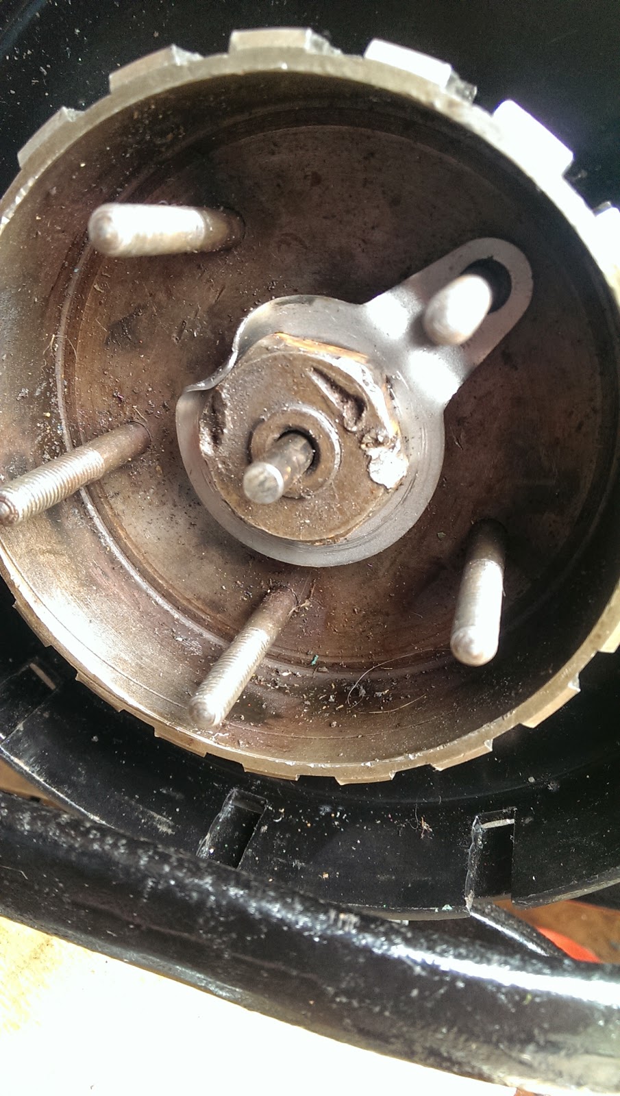
So as I have mentioned previously, my plan was to spin the engine up on the big power drill. I've now done this using a 1/2" square driver with a hexagonal shank in the drill chuck, with the drill set to 2nd gear - slow speed, high torque. The drill drives the engine through the crankshaft nut under the oil pump.


I connected a short hose to trap any fluids coming out of the oil pressure gauge line and take them back to the oil tank. Because of course the timing cover is off, there is a lot of oil in the drip tray which comes from the rear main bearing. 

The plugs are out to reduce the torque required from the drill.


And here it is:

Evidence of oil emerging from the return line. When the drill is running, you can see this pouring out, and you can see it at all eight rockers as well. Its noticeable that the inlet rockers get a lot more oil than the exhaust rockers - Ariel should have adjusted the size of the oil holes (smaller in the inlet rockers) to increase the feed to the exhaust rockers.

After a few minutes on the power drill, the bike is noticeably easier to kick over. Next I refitted the rocker cover studs and I put the tank and the oil pressure gauge back on and ran the test again looking for measurable oil pressure.

At maybe 250 rpm on the drill I am getting something like 25 psi.

Thursday, 14 August 2014

Oil Pressure Gauge

So the electrics are done and the oil system is next. As you can see from this pic, there is a lot of paint in the oil pressure gauge hole:


Easily sorted with a flap wheel in a hand drill (very very low speed)


Lovely


Oil pressure gauge lines:


What's left?

Lots of bits and bobs left to do, but at least the electrics are done. No pictures, but after blowing a couple of fuses due to an ignition circuit fault in the ammeter panel, and some poor connections to old bulbs, I have a fully functioning electrical system. Only a few items left:

  • a link between the brake pedal and the brake lamp switch
  • the speedometer bulb is not working
  • the dynamo is untested
  • the regulator is not connected at the battery

It's mainly oil system now. The sump plate went on last night:


Its a new one with a drain plug, from Drags. Oil filter and oil pressure gauge next.

Tuesday, 12 August 2014

Modifications - Indicators

I've decided to fit Amelia with indicators, in deference to modern traffic conditions. They are typical Lucas look-alikes, and don't look too out of place.

Front indicators retain the headlights


These little tabs are cut from 3 mm thick sheet. They have 3/8" UNF nuts welded to them to suit the indicator stalks:


They weld to the rear mudguard stays:


For wiring up, I am using these 'Japanese Bullets' - small crimp on connectors, fully weather proof.


1.0 mm2 three core is useful for indicators. I like to make an entirely separate loom for the indicators, so that they can be removed easily if another owner wishes to do that:


Put a dedicated earth wire into the shell and attach it to the bulb holder with a ring terminal. By design, the earth path on these repro indicators goes through the plating... Nasty...

So, what you can do is bring an earth wire down the indicator stem to a dedicated earth wire. The earth wire can connect to one of the bulb holder mounting screws. Normally I don't use these modern terminals, but no-one will ever see this:


The handlebar switch is available as a generic indicator switch from many Brit bike outlets. It has three wires: a common yellow wire from the flasher unit, and red and green wires for right & left:


All the wires come into the headlamp where the red & green wires are terminated with a Y connector: one path to the front indicator, the other into the loom heading to the rear. The yellow wire connects to the flasher, which sits in the headlamp shell, protected by a rubber sleeve - MZ style!


The flasher is supplied from a dedicated fuse


Saturday, 2 August 2014

Crimps

Time to make up some fuel lines. I've got 14" of 1/4" ethanol resistant fuel lines knocking around, and some suitable crimp ferrules.


To make a good crimp, you need a little tool which you can buy or, with a bit of 1/2" square barstock you can make your own. The tool is just two 2" lengths of 1/2" square bar, clamped together and drilled for a 1/2" hole, such that there is a semicircle in each bar. V shaped grooves have been filed at four positions around the outside of the hole, and two short 1/4" rods set into the two halves of the tool maintain alignment.

Cut the end of the fuel line square with a sharp blade. Slip the ferrule over the end and push the banjo, tee, or hose tail (with the union nut in place) into the hose, as far as it goes. The fuel line, normally 1/2" OD, will swell out to something like 17/32".

Place the two halves of the tool around the ferrule and squeeze in the vice. The ferrule compresses the tube back to about 15/32", thus retaining it on the hose tail. It produces a better crimp if you squeeze it half way, and then rotate the ferrule/hose assembly 90 degrees in the tool, then finish the crimp.


Compressing the ferrule to less than its original diameter generates some 'spare' material, which swages out into the V grooves we cut. Here is the fuel tap end:


Here is the carburettor banjo:


And here is the non-standard 1/4" fuel filter. Judging by the cr@p I get out of my Bantam tank we will need this:


Monday, 28 July 2014

Dynamo & Split Bullets

Time to hook up the dynamo. The split bullets so beloved of Mr Lucas are a crude but effective design. I thought I'd show you how to use them. These came from Feked, though you can get them all over the place.

Strip the cable insulation so that there is a similar length of bare wire as the length of the bullet:


Push the wire into the wider end of the bullet, and fan the wire evenly over the bullet:


You may need to pass one of the wires through the Tufnol retaining piece before you fit the bullet. Push both the bullets into their socket in the dynamo and screw the retaining piece in place firmly. You will see the bullets slide into their slots:


Then you are done. Fit the dynamo end cover, making sure you don't trap the flexible brush wires in it, and screw the cap down:


Loose Ends

Well, its been an active and enjoyable weekend tidying up loose ends. Thanks go to Patrick Huthwaite who came by yesterday to do the inspection for the Dating Certificate - nice to meet you Sir.

On with the oil tank - the secret to fitting it, is to get it inboard enough to allow the clearance built in the top of the tank to accommodate the frame tube; the secret to allowing this to happen is to remove the nut on the gearbox top bolt.


Next problem is getting the oil lines in. I've realised that most of the struggle I have with this is down to the fact that the strainer I made is way too long, with the result that you have to bend it to get it in and it always catches on the threaded boss in the tank. I cut it down and re-soldered it:


So now, the oil lines go in easily.

I've also fixed the rocker feed oil lines:

And the rocker shafts are sealed:


What else?


Sunday, 27 July 2014

O Lucky Man

Well, there are advantages to being a bit of an eBay vulture...

Gauge, oil line, solder nipple and union nut
My latest purchase is this original Ariel oil pressure gauge, of exactly the right type for the Square Four. This is connected into the double oil line above the cylinder head with a short pipe that comes down through a tube welded into the fuel tank.


You can just see it in the top of this picture. The short line is made from parts from Draganfly - 17" of 1/8" copper tube, two 1/8" solder nipples and appropriate 1/8" BSPP union nuts. You can see the conical nose to the nipple, and the conical seat in the gauge - together these form a metal to metal seal. The nipple is soft soldered to the tube using Baker's Fluid, lead solder and a small blow torch.


That 2 BA stud on the back of the gauge passes through a welded bracket in the petrol tank.

Saturday, 26 July 2014

Slippin' and slidin'

Moving swiftly on...

Not a huge amount to report today, but the gearbox is now filled with a 50/50 mix of Castrol LM grease and 20W/50 engine oil.

Access to the gearbox filler entails removal of the oil tank, which I don't have the knack for yet. The oil tank is very tight to the frame tube, can't be tilted forward because of the distributor and the frame seat tube, can't be tilted back because of the toolbox and the mudguard and is generally a pain...


However, the gearbox is now filled with about 450 ml of oil/grease mix and the oil lines have their hose clips in place - modern ones unfortunately.

Tomorrow we will have a major step forward - we are having a visit from a local AOMCC member, Patrick Huthwaite, whose inspection is the next step in the registration process.

Hopefully it won't rain.

Thursday, 24 July 2014

Mighty Morgo

Today I fitted the Morgo oil pump made by Autovalues Engineering from Bradford.

The Morgo is a gear type pump, and is very nicely manufactured, well packed and is provided with a comprehensive set of instructions. While there are several Morgo rotary pumps for other Ariels & Triumphs, the fitting kits and instructions are bespoke to the model you are fitting. Very nice quality, well thought out.

The pump comes with a fitting kit, consisting of the left hand drive nut, a set of shims, a gasket, two tab washers and two mounting bolts


This is the drive side of the pump, showing the Oldham coupling used to drive the pump from the camshaft.


And here is the drive nut for the pump. Those slots are closely toleranced to prevent rattles and wear


Here it is in place. I've got it fitted with the original studs at the moment, since I don't like the idea of wearing threads in the soft crankcase to remove a service item but in practice you have to engage the pump coupling before bolting up - it is close fitting in its slots, as it needs to be, and this makes the bolts supplied with the pump the only practical way of fitting it.


I need to prime the pump - so I will refit it with the bolts supplied with the pump.


Tuesday, 22 July 2014

Throttle Cable

I've had the throttle cable set up like this for a while:


As a few folk on the AOMCC forum have pointed out, it doesn't work very well. First off the cable outer doesn't have a good abutment in the stainless steel bracket; secondly, the volute spring (granted it is the wrong one) has way too much internal friction to return the throttle successfully; thirdly, the cable run is poor, both due to the bracket and the volute spring.

But mainly, with the Solex carburettor and its butterfly throttle valve, the cable return spring is the only method of closing the throttle - so if it is not working well, you are going into the back of the braking car in front (and I have done that before) or that expensive rebuilt engine is going to disappear in a mass of tangled aluminium.

So, now I have this:


I have removed the volute spring entirely, and I have a stiff coil spring in its place. It's attached to the dynamo strap with a stiff wire link, and it has a little brass sheet link to attached it to the carburettor cable clevis pin. The throttle returns beautifully now.

I need to adjust the cable path by bending that bracket a little more, and I'll plate that spring later.

Sunday, 20 July 2014

Great strides...

Masses done this weekend.

I started by trimming up the HT leads and setting the distributor position, followed by the ignition timing - easy with the timing cover still off.

Next I stripped the primary drive & the clutch, pinning the engine shock absorber and bolting up the inner case.

I pulled the outer cover off the gearbox, and removed the gearbox mainshaft. I wanted to check that I had greased the sleeve gear, which I had - too many stories of those bushes seizing! I thoroughly greased the gearbox change mechanism and the kick start parts, before bolting everything up and fitting the clutch.


For some reason the new clutch centre nut does not fit - tight on the thread. I'll have to use this old one, for extra 'patina'...

Next, the clutch cover. This has never been fitted with the exhaust in place and, as predicted by several AOMCC forum members, the exhaust fouled the clutch cover.

This was easily remedied with a little metal work, and I produced a professional looking dish in the cover with a hardwood block and a deep socket.

I fitted the rear chain and chainguard too, using my usual ty-wrap method:


Next, the smaller oil lines. These are very soft copper and are easily bent by hand.