Wednesday, 29 April 2020

W/NG Silencer

One day, I was walking up the road to my workshop and found a piece of rusty perforated steel in the road, squashed quite flat. I thought nothing of it.

Weeks later , I was musing over the efficacy of the W/NG silencer and looked inside the taailpipe only to find a similar piece of metal, though this one was partly tubular. The penny dropped.

Apart from this shred of perforated steel, there as nothing else in the silencer.

Burgess silencers, as used by Ariel, are supposed to look like this:
The principle employed in this type of silencer is the absorption of soundwaves transmitted by multiple reflections from the inside walls of the pipe. It uses an expansion chamber which surrounds a portion of the straight pipe system, perforated to allow escape of the gases into and out of the chamber, which is packed with absorbent material to diffuse the pressure and deaden the sound. 

One particular advantage of the straight through pipe is that it is not liable to partial choking, through fouling of the absorbent packing; the gases will always get through without hindrance or increasing back pressure, though the effectiveness of the silencer will suffer. 

An alternative failure mode is rusting and the loss of the absorbent material, leaving you with a simple expansion chamber which I suspect would not be really large enough - expansion chambers should be something like five times the swept volume of the engine.

So, there was no option but to cut the end off and repair it:


We need to replace the perforated pipe, which is easily available on eBay:


Unfortunately that's where we run out of pictures. I wrapped the perforated pipe with fibre glass blanket, wrapped with wire to hold it in place while I slid the silencer body over it.

The last bit was to run a peripheral weld around the body to cap joint, and that was it. The simple finish of a WD machine is a real help sometimes.


Tuesday, 28 April 2020

QR50 - Retrieving Splines

Well, as I had the lathe set up with the ER25 collet chuck and the fixed steady (for the crankshaft threads) I thought I would prepare the kick start quadrant for the spline repair.

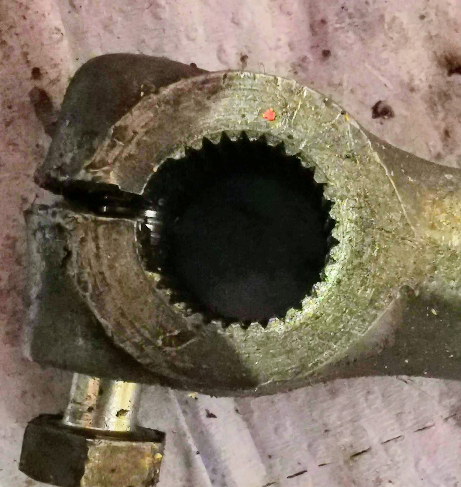
Like a lot of bikes, this has suffered the usual calamity of allowing the kickstart to come loose, fret  and eventually turn on the splines. This one looks like there has been some weld repair, and it is full of holes...

I have a Honda Express transmission which I had thought would provide a replacement - unfortunately, it looks like Honda decided this design was inadequate as the Express quadrant is much bigger in this area.

We'll have to fix this one.


First of all I will have to put this in the lathe to clean up the mess


Then, I will have to build up the missing bits with the TIG set, followed by restoration of the splines. Options could be:
  • milling, using an end mill in the lathe and indexing the part in the rotary table
  • grinding, using a toolpost grinder
  • shaping, using a suitable tool and indexing using the dividing attachment
  • machining a plain journal and using a axial pin to provide the anti-rotation feature 
I could also make a new shaft to the correct size and make the splines in that, to avoid the building up operation - but then I would have to remove the old shaft and re-weld the new one.

Turning off the damage is pretty straightforward:


I need to look at the short taper behind the spline as well:


With it cleaned up, I can think about welding:


In this first picture, I have laid about 4-5 mm over the end of the shaft, with the machine set at 75 A. This is half a ball, and of course I need to build up a cylinder with a square end. This will probably need some more work:


Laying metal over the diameter:


Laying more material into the diameter, about the tapered section which will need recutting:


This is the kickstart lever. The major diameter of those splines is 13.5 mm and it looks like we have a 30° spline. Inside diameter is about 13.2 mm. It's quite difficult to count the splines, but it appears the full circle would have 30 splines.


Here, I've turned the weld down to a tad under 14 mm, to see where we are:


Here's the length, turned to 18 mm:


We need to build up more in various locations. I've decided to dispense with the peripheral groove, since I don't need it - I can decide where I want the clamp bolt clearance and cut a small slot in the appropriate location later:


Having built it up some more it is time to turn to the final size:


We use the usual dividing gadget to set the lathe up for dividing the 30 serrations:


Here's the tool set up for cutting the serrations:


Here's the first few, first stage of cutting. I'm using three passes at 0.075 mm per pass which in theory will give me 0.225 mm height to each serration, which equates to an ID of 13.05 mm. In practice, clearances and flex in the lathe will prove this is not sufficient:


All cut to the initial stage. Part way through this stage I tightened up the fixed steady which has had the effect of making the later serrations deeper than the initial ones - look at the last ones I cut at about 9 o'clock, against the first ones, about 11 o'clock.


Here's another view. You can see that the serrations are still truncated - the next stage needs to be deeper.


These are 0.05 mm deeper. You can see the form has taken shape by virtue of the small chamfer at the nose of the shaft:


And that is it - or it would be, if mating the two parts had not revealed that the Honda design has 31 serrations, not 30...

It should look like this:


Here we go again:


QR50 - Wiring

It's a bit early to be looking at wiring up the QR50, but since we are on lockdown and my workshop is a few streets away I have resorted to bringing stuff to the house to work on. It's good to bring the wiring indoors - it's a nice clean job that you can do at your desk in the study.

This is virtually all I have, apart from the toasted generator stator I showed you in another post. This is the CDI unit:


And here it is again with all that insulating tape removed. If you look closely, you will see that some of the wires have been cut very short:


This is the whole 'harness', minus the sleeving. There isn't much to wire up on a QR50, but it is not supposed to look like this:


Before we start though we need a circuit diagram. Through a lot of research, Honda parts lists, generic CDI system diagrams and looking at the charred remains of the original loom I have come up with this:


There's a lot going on in this diagram, besides the connectivity of the various parts. Let's look at the way the system functions:

  • The Black and White wire (BW) wire is the exciter - it provides AC voltage to the CDI module
  • The Blue and Yellow wire (UY) is the trigger - it uses the hall effect sensor in the rotor to tell the CDI unit when to fire the coil
  • The kill switch earths the exciter coil through a second BW wire, preventing the ignition from working.
  • The Green and Yellow wire (GY) is connected to a micro-switch in the rear brake lever. According to the user manual, the engine won't start if the brake is not applied, and there is a spring loaded lever to hold the brake applied while you start (this disengages as soon as you squeeze the brake). I assume (at this point) that the switch is intended to break a ground connection when you apply the brake, but that this has no effect when the engine is running...
  • The Black and Yellow wire (BY) is the wire to switch the ignition coil.
  • The Green wires (G) are grounds.
In addition to the functionality, I have used this diagram to indicate cut wires - each cut wire has a number (1 to 16), and each cut wire has a connector (male, female or double female). The harness layout is shown in a simple sketch with rough dimensions; I have shown a length against each cut wire and summarised these to determine the total length of each colour. This list, along with the list of connectors, tells me what to order. I have followed Honda's practice of using the same 1.0 mm² wire throughout.

I'm going to use original type Japanese 3.2 mm bullet connectors throughout. These work beautifully and are protected from the weather - but you must select them according to the wire diameter.


Here are most of the parts we need:


First, I am using some tube crimps and solder to extend all the wires from the CDI unit to match the only remaining original wire, the ignition trigger. This is often tricky, as 40 year old wires are often too dirty to solder; this one has been OK, probably thanks to all the insulating tape.


I've protected these joints with heat shrink sleeving. I bought a selection of 8" lengths in various colours from eBay, and very useful it is too.


This is the CDI unit, finished with sleeving and boots as the original was. That large boot with the section change was made from a short length of heat shrink sleeving, partially shrunk over a small bottle of glue:


The parts list calls for a harness from the CDI unit leading up to the headstock area - this connects in the two handlebar switches.


Here's the finished stator:


Now I have the bike partly assembled, I can lay the harness out on it to see where the parts are routed and to ensure that I have sufficient length in each of the harness parts.


Monday, 27 April 2020

QR50 - Assembly

It's a grand time in any project - where you are casting around for jobs and realise there is little left to do on the components. I'm at that place now with the QR50 - the crankcases are closed up, the frame is painted, the forks are done, the shock absorber is done, the centre stand is done and most of the transmission components are ready.

Right now, I can't start the wiring; I can't assemble the generator, the oil pump or the carburetter, I can't look at the exhaust or the generator cover, both of which are significant fabrication activities. What I need to enable these jobs is to put the main elements of the bike together.

Here we go.

First job is to prepare the transmission. The nut shown at 8 o'clock is the fulcrum pin for the rear brake shoes - this is inaccessible when the transmission is assembled:


Here's the fulcrum pin in position:


Next is the output shaft, with a bit of oil to lubricate the oil seal. The bearing is sealed and doesn't need separate lubrication:


And from the other side:


The crankcase is together, and this bracket bolts underneath to carry the centre stand and the rear shock absorber:


We can then fit the main frame spine and sub-frame on top of the crankcases:


The single shock absorber bolts in next:


Here's the other side:


I've fitted the barrel and cylinder head, to get a feeling for the space they occupy:


The inlet tract and reed valves are on place as well. Stepping back:


This is the oil pump drive fitted, which brings us to a close for the moment. The oil pump needs painting and some oil lines adding; I can see the routes and lengths of the harness now and once I have painted the transmission cover and finished the kickstart shaft I can assemble the transmission.


QR50 - Closing up the crankcases

Having put the bearings in, all I have to do to close the crankcases and move on with the project is fit the crankshaft oil seals. These allow the crankshaft to pass through the cases but remain sealed, so that the crankcase compression upon which 2 stroke operation depends is as effective as the designer intended.

Identical seals fit into each crankcase - they also came from Simply Bearings:


You can often push them part way by hand, followed by a little help from a mallet and suitable drift. On the generator side, the seal goes a little way in - the recess locates the generator.


Before you go any further, if you have not done so already, is to dry fit the crankshaft to the cases. Make sure the cases fit together and the crankshaft is free to rotate when the cases are closed up.


Don't forget that the crankshaft needs to be the right way round! It will fit both ways, but this worm drives the oil pump. Oil the seals, bearings and this worm before you attempt to assemble the cases for the last time.


Next job is to seal the crankcases. I'm using some Threebond 1215 silicone gasket to seal the cases. It's grey, discrete and rated at 250°C. Ample for this application.


This is spread thinly over the sealing surfaces and around the bolt holes, followed by mating the cases together and pulling down the bolts.