Monday, 28 March 2022

Charlie's Shed - Making a sidestand

 The sidestand fitted to Anstey-framed Ariels is a poor affair that does not extend very far from the frame and has a very small foot which combines to make the use of the stand a very precarious and risky operation. I never use it. 

However, the bike is a heavy old thing which would benefit from a decent sidestand so in this episode I'll show you how to make one.

I bought a leg, a while back, from eBay. It's from a Suzuki TS125 trail bike, so it is very long and it came with a spring and a M10 x 1.25 bolt. Doing this again, I'd probably buy a Triumph or Enfield leg as I ended up cutting a lot of length off this one.

The sidestand is going to bolt on, but I'm not a fan of clamp on types so this is going to bolt across the two bottom frame rails forward of the sump plate. A piece of steel bar, 6 mm x 35 mm spans the frame. I start by putting a 45° bend in a short length at one end, to start to get an idea of how it will look on the bike and what sort of leg length I will need, where it will sit in the 'up' position and where the stops will need to be. I drill a 10.5 mm hole for the bolt and fit the leg:


The first decision I make is that the spring will be underneath, not above the leg as Suzuki had it. I'll cut the peg off and smooth the area:


While the 6 x 35 mm flat bar can provide the 'down' stop, it needs extending to provide the 'up' stop. I make a piece with a double prep and weld it on:


Some shaping with hacksaw, files and the linisher gives us two stops:

The stand is going to be held on the frame rails with three 1/4" U bolts, one on the drive side and two on the timing side. Here's a trial fit of the first one:

With the assembly in place we can look at the leg length, and the angle it is going to make with the ground. Obviously if the stand's touch down point is further away from the bike's centreline, the bike is more stable. We don't want the stand leg too short, but leaving it like this won't allow the bike to lean enough.

Next, we need to stiffen that bar. It's stiff, but this is a heavy machine and we don't want a rider sitting on the bike while it is on the stand opening our stand bracket out. The stiffener is a piece of 20 x 3 mm flat bar


The stiffener also provides somewhere to mount the spring lugs. I made these from a bit of 10 mm round bar on the mini-lathe:


One of the key issues is to get the lugs in the right place such that the spring holds the leg firmly in both positions, without the spring fouling anything as it moves:

There was way too much slop between the stand leg and the mounting bar. I built up the bearing surface with weld and cut it back on the linisher to get it to about 7 mm

It's much less wobbly. Obviously wobble here will affect the lean of the bike when it's on the stand.

Time for another fitting. At the previous trial fit, I marked the position of the timing side U bolts, so now I can drill the holes. I haven't yet trimmed the mounting bracket, but I have trimmed the leg. Here are all the bits:


The bike has a lean of maybe 5°, which is fine.


Time to start finishing the leg. Here's the foot, cut from a bit of 3 mm sheet. The sheet happened to have a hole in it, I'll fill it up later:


Gosh that was quick. In this next picture, the foot is partially welded on and I have made the foot finder from some 10 mm round bar and another bit of 3 mm sheet. To start with, I fitted the stand to the bike in the up position and held a 200 mm length of the round bar in place, deciding where I wanted the foot finder - it needs to come out behind the foot rest and to do that I needed a bend. Once I had the bend formed I held the round bar on the foot with a spring clamp to see if it was in the right place, and I was able to see how long the bar needed to be and where on the foot it needed to be fixed. I tacked it on the foot.

Next I made a 25 mm square pedal, and curved it a little to emulate the shape of the brake pedal. I tacked that on the end of the bar and refitted the stand, which revealed various issues. These were resolved by removing the leg and holding it on the vice, heating the round bar to perform the bends I wanted - the bar curved around the exhaust, but not tightly enough, and the pedal was not square to the bike in two axes. A bit of heat soon fixed those issues. 

That's it for now. The stand is back in position and working:


I'll run around with it for a while and see how it goes. I still need to ease the 'u' bolt holes on the timing side and trim the end of the bracket before painting, but for now we need to shake it down.

Friday, 4 March 2022

FH Dry Build - Magneto Cutout Switch

There's lots of jobs to do on an old bike project - some dramatic, some messy, some tedious, some hardly noticeable. One of these is the magneto cutout, which is a small Lucas 76207 horn button mounted in a folded steel bracket to one of the handlebar clamp studs. It's here:

You'll recall I made some nuts last week - one of these was the locking nut for the cutout button:


The bracket will be a bit of 2 mm cold rolled sheet, but its a bit of an odd shape as it has to appear from under the top yoke, go forward under the handlebar and then pop out between the handlebar and the casquette. It took me three goes to get it right in cardboard:


I made the next prototype in 0.8 mm sheet which I could cut with snips and fold easily:


This looked OK but the switch wasn't quite in the right place:


It took me two more goes in this sheet before I felt confident that I wouldn't be wasting time if I went to the full thickness. Of course, at 2 mm thick it was going to need a bend allowance and it's straightforward to build that in during the marking out stage.


Here's a close up after drilling - you can see the double lines showing the position of the bends. I use a bend allowance equivalent to the thickness of the material - in this case adding 2.0 mm to each bend.


Here it is again, having been cut out with the hacksaw, filed and linished to the final shape:


I didn't take any pictures of the folding in the vice. I was careful to use the smooth jaws, have the bend line exactly aligned with the top of the jaws and to observe the bend forming as I pushed it over, such that the bend was formed between the two bend lines.


That's it. I've added it to the list of small bits to be zinc plated later.


Thursday, 24 February 2022

Charlie's Shed - Making Nuts

 This week, I have been mostly making nuts...


These are the special sleeve nuts for the front stand - only the SQ4 has the correct one, so, since the same part number has been used since 1928 I have made four - one for stock. 


These are 3/8" CEI reduced hex half nuts, in this case for the Huntmaster magneto cutout button. I made three - two for stock. 


Threading these on the lathe was being difficult - the 5/16" CEI taps are dull and this is 303 stainless. I started them in the lathe and finished them in the vice. 

Either I need to learn how to sharpen taps or I need to replace them! 


Thursday, 3 February 2022

FH Dry Build - Front Stand

Amidst various domestic and railway activities, the FH Dry Build marches forever onward - and I am beginning to run out of jobs. Did I really say that out loud?

I took a series of pictures for the dating certificate and this one reveals graphically that the front stand is wrong - it's either not Ariel, or perhaps is for a bike with a smaller wheel, though I can't see that somehow. The FH has a 19" front rim and none of the bikes I am aware of use a smaller rim than that, apart from the Leader & Arrow neither of which use a front stand.

Anyhow, it has the right fitting at the rear and is the right shape, so I am going to use it.


Removing the stand in the safety of the workshop reveals it is about 3/4" too short:


What I have done is cut both legs as square as I can and trimmed them up on the linisher. Then, I've taken a piece of 5/8" x 16 swg tube and cut two 3/4" sections on the lathe; I've also cut two pieces out of a scrap footrest bar (which was bent) to support the spacers and keep everything aligned:


I've set it all up on the bench, and cleaned the areas to be welded on the wire wheel. There's a bit of 5/16" bar through both ends to keep them aligned while I tack it together:


Two autogenous butt welds on each side, 40A:


And there we go, problem solved.

All we need now are a couple of Thackeray washers and I can make the pivot bolt spacers on the lathe. 

Here they are now, 5/16" ID, 3/8" OD and 7/16" long 303 stainless:

Bolts are 5/16" CEI x 1". This is how they fit:

The stand pivots around the spacer and the Thackeray washer prevents it all rattling. You can drop the stand by loosening the single nut at the back of the mudguard.


Monday, 31 January 2022

Tools - new connector for the FH tyre inflator

 Some of you might have seen my post on Thapex tyre pumps - click here, and the post on making pump washers. As I said before, pumps bought from eBay, autojumbles and car boot sales arrive in unpredictable condition, cracked, with missing or tired washers and almost invariably without their connectors.

This article is about making those connectors, but first a word on terminology.

While researching these things, and looking for a longer pump hose that I could buy, I came to realise that the cycling world doesn't recognise the word 'hose' in connection with cycle pumps - indeed, cycle pumps are a bit passé these days having disappeared in favour of CO2 powered inflators. No - the cycling world seems to use the word 'connector'.

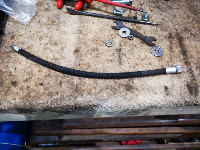
So, here we go. First we need a bit of hose - not too difficult, you can buy 1/4" braided fuel hose on eBay in various sizes - I bought 500 mm of 6.5 x 3mm black cotton braided hose for the princely sum of £2.68.

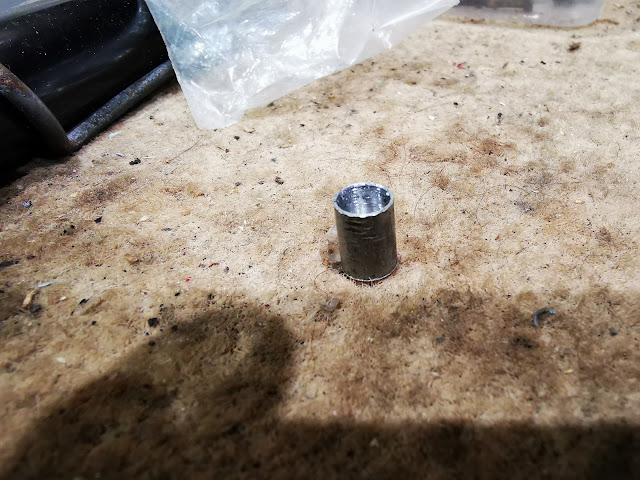
The difficult thing is always the ferrules, whether it is for a push bike or a motorcycle fuel line. They are either hideously expensive or just not available, so along comes another skip raid. Some time in the past I had acquired an aluminium cycle rack, the kind you put your shopping on and cycle home from town. It was full of weld but I had cut it up and stored it in my metal stock bin. It was 8mm OD. It machined well enough to make a couple of ferrules very easily - that is a 7 mm hole in the middle, they are 10 mm long and the 7 mm bore stops 1 mm short of the end. The end is drilled through 4 mm.


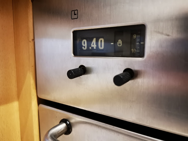
The aluminium bar gave me two replacement cooker knobs as well:


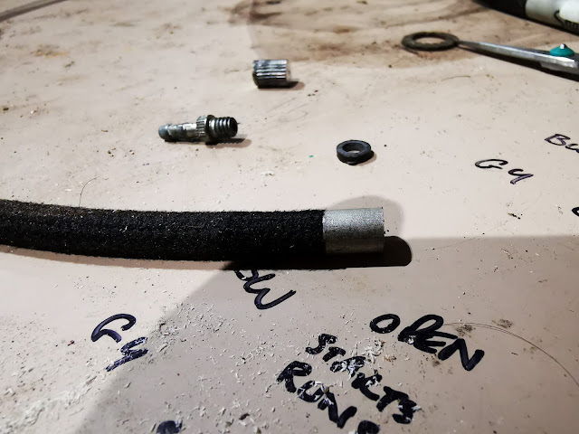
The ferrules fit nicely over the braiding:


The crimping was done in the three jaw chuck on the lathe:


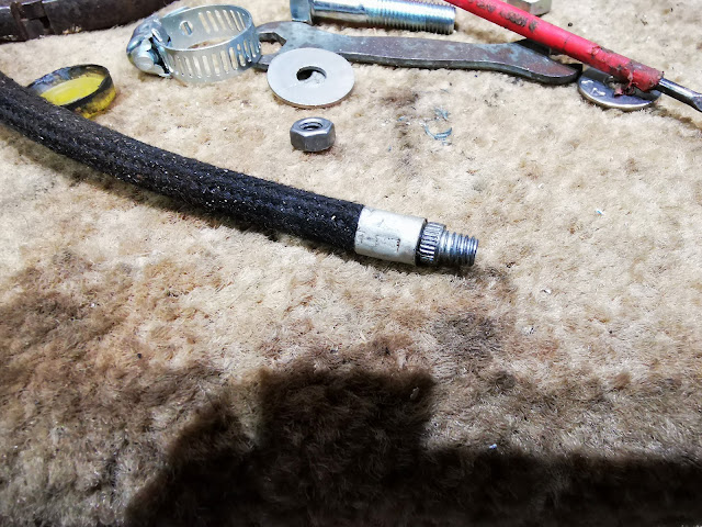
And the completed article. The length wants to be as long as possible but is defined by how much you can store in the pump:


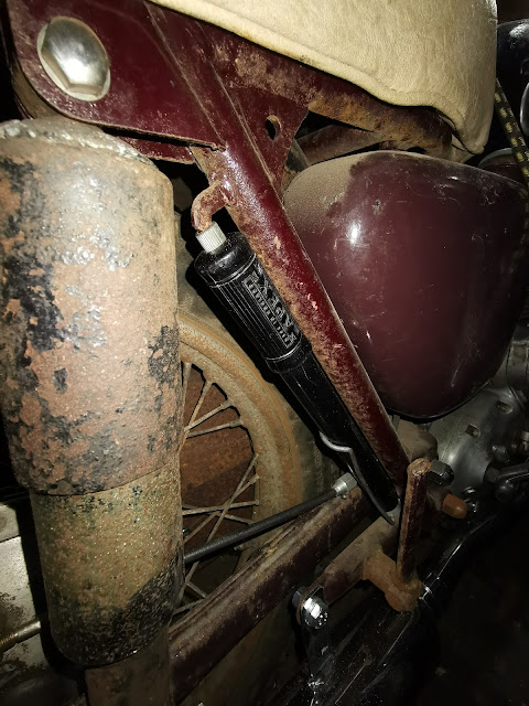
Here's the complete thing on the bike:


Sunday, 30 January 2022

Tools again - New washer for the FH tyre inflator

Some of you might have seen my post on Thapex tyre pumps - click here. As you might expect, pumps bought from eBay, autojumbles and car boot sales arrive in unpredictable condition, cracked, missing or tired washers and almost invariably without their connectors.

Some while back, I bought a nice new washer purporting to fit one of my pumps and it sat on my desk for a number of years until I came to fit it - which of course it didn't. It's about 1 mm too small.


So, time to roll out a lost art shown to me by my grandfather Leslie, who was a serious cyclist - he worked at the docks during the war, and having relocated from West Ham to Ewell had a 18 mile commute to work, which he did twice each day on his bicycle. What you do is this:

Start with a piece of leather, in my case the cuff from an old Jalatte safety boot. For a 7/8" pump, you will want a disc of about 30 mm diameter which you can cut with scissors, or however you want.


Next, punch a hole in the middle. The washer screw in a Thapex pump is 2BA, so a 5 mm punch will do. Next, we are going to form the leather into a cup; before we do that we are going to reduce the thickness of the leather around the edge, a process called 'skiving'. You use a very sharp - no, very, very sharp knife to slice a layer off the surface, reducing the thickness at the edge to perhaps half what it was (the boot was about 2.4 mm thick).


Fix the retaining washer in place with the screw and add a second washer on the back - I used an M5 repair washer on the back and an M8 washer under the screw head, to support the flat part of the washer at the right diameter - all clamped tight with a 2BA nut. Drop the whole lot in a cup of water for a few hours until it is soaked through.


This is a 22mm Jubilee clip - the inside diameter is set to match the inside diameter of the pump. I have pushed the wet washer into the clip to form the cupped shape. Make sure it is square and leave it to dry out.


And that's it - next day, we have one perfect cup washer. I smear the washer in neat's foot oil and assemble it straight away, before it has a chance to return to it's original shape.

Here it is installed: