Friday, 28 April 2023

SQ4 Clutch Investigation

 After the Blakeney run, Tom reported that the SQ4 clutch was slipping when he got home - he couldn't get it to go over 50 mph without the clutch slipping. 

We rebuilt it using the new plates from the W/NG, which got it's old Ferodo plates back; middle grandson Felix helped with the job:


We made a little pointer to show the pressure plate was lifting squarely:

Oddly, it wouldn't function with the old pushrod - We had to add 1/8" to the pushrod length, having found the original 12 3/4" wasn't long enough but 13" was too long. We settled on 12 7/8".

A month later, we had the opposite problem where it wouldn't disengage - Tom took it apart again and adjusted it, and all was well. Sticky new plates, or some intermittent fault?

Wednesday, 26 April 2023

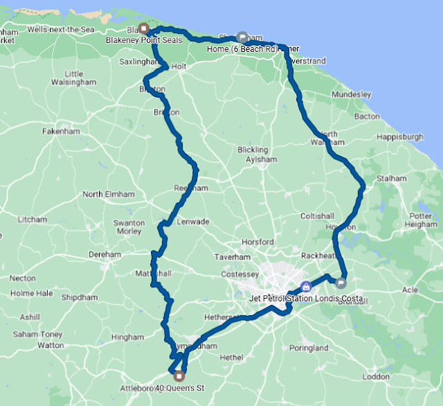
VMCC Blakeney Run

 Sunday brings the first VMCC run of the year, the first of many I hope. The W/NG is at son Tom's house with a dead speedo, so the first trip of the day is to go down there, meet up and replace the speedo cable.

That done, it's off to the start point at Spooner Row just outside Wymondham via a petrol stop.


We arrive on time (for the first time!) and sign on, grab a cup of coffee and are welcomed by the crowd falling easily into chatting about our bikes and where we have come from. One or two remember us from Letheringsett 2022 and from a Blue Sky run I did on my own a few years back. At 11, we set off for Blakeney, a 40 mile trip through the Norfolk countryside. Tom leads, as both bikes have route rollers now:


Tom leads that is until his speedo cable snaps again at 7 miles into the run, 27 miles into the day. Tulip sheet navigation is tough with no speedo! I take over, and we arrive safe and sound at Blakeney Quay, for coffee and a burger from Birdys Bakehouse, and very nice it was too.


Tom shares my enthusiasm for Scott motorcycles:


We are joined by one of their owners, who gives us a guided tour of their eccentricities:

There are some more pictures here, on the Norwich Section VMCC website.

Tom and I part on the way home - he's riding the SQ4, as there is a lot of oil coming from the rear of the top end of the W/NG and the speedo needs fixing again. That's 85 miles - hardly fault free but neither of us stopped unexpectedly.

Bring on the next one!

Wednesday, 12 April 2023

W/NG - kickstart repair

 There's always something. There I am, minding my own business and riding the W/NG to my current house renovation project and thinking I've done most of the work on it, when the kickstart fails. It sometimes jams, failing to move the engine and feeling very solid. This is why:

See the first tooth on the quadrant? It's jammed against the pinion. The second tooth will do this too and the way to remedy it is to put the bike in gear, move it a fraction (to move the mainshaft pinion) and kick again, when it will work.

Trouble was, this time I wasn't paying attention and gave it a mighty kick, breaking the quadrant. Damn thing is only 80 years old:

Ariel owners are blessed with the splendid AOMCC, one of the most friendly clubs I have come across and with a superb spares scheme. I had a new quadrant in two days, and given that I had asked the gearbox spares man to find me a new one on Easter Monday (I'm writing this on Wednesday) I think that is pretty impressive.

It's all fixed now.

Friday, 7 April 2023

MZ TS125 - Petrol tank rust repair

This is going to be a bit of a leap of faith - my first fuel tank repair. This is an MZ TS125/150 tank from son Thomas and has fortunately been empty for many years, having been stored in the open in someone’s garden - no wonder it’s rusty.

It’s made from two deep pressings, with a third to form the arch over the frame top tube. There appears to have been a butt weld between the two halves, which has corroded to holes. My plan is to take out the whole weld, all the way around, along with a 1/2” strip either side and then let in a 1” strip of 0.9 mm sheet. I make no apologies for mixing units - anarchy is alive and well here in the workshop.

Using the little Dremel discs to cut out the strip makes the job easy. It’s ideal if you can keep the sides parallel, since then you can make a filler with parallel sides and have a minimal gap which will require minimal filler material. 


I held the sections in with magnets while tacking up:


The first section went in OK - I welded in short sections to avoid overheating the material and causing distortion:


It’s quite a slow job, but if you make sure you have a good position as you weld it’s not too difficult.


I used the little belt sander to clean the welds back:


Not a bad result, though it will need a skim of filler:


Pressure testing revealed two pin holes in my welding which were easily fixed. More worrying is a further pin hole behind one of the brackets, which is completely inaccessible and looks like it might turn into a bigger hole:


I’m going to use a tank sealant to fix that. More later.

Saturday, 1 April 2023

W/NG - Horn Repair

 Well it's been a week of cracking through little bike jobs, alongside welding up rust holes in the fuel tank of yet another Eastern Bloc two-stroke, this time an MZ TS125 - but more of that later.

For some while the W/NG horn has been a little touchy, because the horn adjuster doesn't work very well due to a stripped brass lock nut, though I improved it a lot in the middle of last summer by squashing the nut slightly. It has an odd thread, 0.209" x 36 tpi which I found by luck on eBay - it's a bicycle tyre valve core thread!

The adjuster lives behind the tone ring nut:

The one that was fitted had a 10 mm hexagon and was a half nut - it may have been 0 BA at one time and forced on, but I suspect it was the original as it was cadmium plated, or perhaps faded nickel over brass. I made a new one out of 0.445" EN1 hexagon bar, turned with a significant chamfer on one side to clear the inside of the domed tone ring nut:


It works beautifully.


That's it for a bit on W/NG repairs. I still have the bum pad to make and the dynamo bearing felt to put in, and I have to monitor the new seal in the decompressor. The jury is still out on the field stand springs - they still have a safety chain on, though it hasn't made another bid for freedom since I tightened and retempered the bottom spring.

Tuesday, 28 March 2023

Charlie's Shed - W/NG Dynamo Repairs

 Some while after fitting the new headlamp and instrument panel, I became aware that the ammeter rarely showed a charge. At the time, I assumed it wasn't centring properly and resolved to pull it out and adjust the needle. However, obsession being what I'm known for, I kept an eye on it and eventually realised the needle intermittently showed a charge. There had to be something wrong.

Following the usual checks (voltmeter on the battery, linked D & F cables with voltmeter to earth, connectivity checks) I realised the dynamo was struggling to go past six-point-something-small volts.

I went inside, and here is what I found:


That's it - goop and copper dust. I sprayed it with brake cleaner and put it back on the bike, with the brushes now sliding in their holders. A few trips showed a steady improvement, but it still wasn't right. Waiting until I had a few hours I could dedicate to it (it's in daily use, more or less), I took it off again and stripped it down to find the shims that one of the previous owners had fitted (and I had re-fitted) to accommodate the non-standard bearing had moved and cut into the commutator, shorting out the segments intermittently.


I resolved, after much deliberation, to bring the bearing arrangement back to standard. As part of the process, I cleaned up the commutator on the lathe:


The bearing came off after a few minutes with a grinding wheel in the Dremel. It wouldn't budge for a puller, but the Dremel cut through the outer race easily so that I could split it and pry off the ball cage without damaging the segments. I ground the inner race tangentially until I was almost through to the shaft, when it cracked and came free. The shaft was in good condition underneath, measuring a hair under 7 mm - odd, because the Lucas parts book suggests the internal diameter of the bush at this end is 8 mm. This must have been enlarged post war - this dynamo is marked 1943.

In a footnote to this, I realised the E3L fitted to my FH has ball bearings at both ends. I wonder if this E3HM has an E3L end bracket?


These are the culprits - two pieces of thin steel:


I made a drift to knock out the old bush:


I turned the new bush out of a bit of SAE 660 phosphor bronze I had. This is a bearing bronze that is considered the standard bearing material for light duty applications. It is easily machined and the bronze alloy is hard, strong and resistant to wear. Apparently it also conforms well to journal irregularities and is less dependent on lubrication than other alloys.

I drilled it 6.5 mm and reamed it 7 mm:


The old bush measured 11.2 mm outside diameter and pushed out easily. I made mine 11.3 mm and whilst it went in with no trouble, it was considerably tighter than the old one. I reamed it again when I had it fitted and deburred the ends.


The clean armature journal fitted beautifully and I reassembled the dynamo, pausing to look at the drive end which seemed to have a lot of end float, though in fact it was around 0.5 mm.


I attempted to motor the dynamo on the bench, but unfortunately the only loose 6V battery I had was completely flat. I refitted the dynamo to the bike, and started the engine to find the ammeter kick over to the 'charge' side with a few revs. Job done, except for the felt washer around the bush which I don't have at the moment.

Another small job I wanted to do was bush the end cover retaining screw hole (3/16" BSW) which has stripped. Unfortunately there is not enough room to fit my preferred M8 bush, which is plenty big enough to tap 3/16" or even 1/4" BSW if you have to, so I re-tapped the hole M5 which is a little bigger than 3/16". I'll have to think about that some more - perhaps go for an M6 brass bush which I can drill and tap 3/16" BSW.

Wednesday, 22 March 2023

FH -Seat Base Repairs 2

 Following the repair of the FH seat base fixing screws which I wrote about recently, I found a bit of time to finish the repair of the rear end.

You can see how the seat is constructed here. The large shaped pressing that you sit on (Ariel were making more use of steel pressings in the late '50's) is spot welded to two angled sheets which sit on the frame rails and carry the mounting holes. Those angles are closed with two quadrant shaped pieces which rot away.

I cut them out:


Using a bit of cardboard, I made a template to get the shape right:


This pale blue metal was an old bread bin, which has given me the air box for the QR50 amongst other things. It's about 0.9 mm thick and is easily cut with the Wiss snips, followed by clamping the two together and shaping with the linisher.


The paint burns off easily and it's remains are cleaned on the wire wheel. They just need tacking into place:


With both done, you can see how the back of the seat is closed off. The cover will actually come down over these plates, but more of that when it is painted.

I mustn't forget to smooth off those welds before painting!

Wednesday, 15 March 2023

W/NG - Field Stand Springs

 Whilst the field stand on the W/NG is a fine thing, I don't use it very much as it's a bit of a nuisance to get it down and back up again. The stand is not quite as shown in the factory parts books and is probably not original.

The same could be said of the spring clip, which looks a bit like the earlier type but is too short - it’s not only stiff but now that I have the panniers fitted, it allows the stand to foul the pannier frame bracket.

So, inspired by fellow W/NG owner and YouTuber Alan Moore, who compiled an excellent instructional video on this subject, I resolved to make a pair. You can buy these clips now from various sources (including the AOMCC Singles Spares) but I decided carry on with the plan to make my own to prove that I could.

I started with a simple bit of wire to develop the profile of the spring:


That gave me the length and the shape I would need and I used this to make a card template. Following Alan’s example, I bought a couple of lengths of CS95 spring steel from eBay, and used the Rothenburger MAPP torch to normalise them, by heating to cherry red and cooling in air.

This process left the hard spring steel soft enough to drill and to cut to shape with the snips.


With the blank cut and drilled I could bend them to shape. The first one took a bit of faffing around with bits of round bar in the vice, pliers and swearing; for the second one I welded up this little tool which made the bending much easier. I left the sharp bend near the mounting holes until last.


Using the tool, it was easy to make those reverse bends. It’s the fact that they are so close to each other that makes bending the spring difficult without a pair of bars fixed close together.


Once I had both springs bent up, I could fit them to the bracket on the bike and ensure that:
  • The stand would be gripped adequately
  • The ends of the spring would be open enough to allow the stand to be pushed in
I messaged Alan through YouTube to ask if he had had any problems with the bends opening during heat treatment - he hadn’t (and nor did I).


I built a little barrel furnace out of a 5 litre beer keg, some ceramic insulation, a fire brick and some fire cement. The first step was to heat the springs cherry red; you can see the torch is low on gas in this picture as the shroud is glowing. I swapped gas cylinders after this and used the almost-empty cylinder for tempering.


Next, quench in oil:


After cleaning the oil off, you can test the hardness with a file. The file just skates off the hardened steel and will not mark it. Next, you clean the oxide off with Scotchbrite so that you can see the colours form during tempering:


Next job is to temper the whole spring to 350°C, which is the blue colour you see here and quench in water to stop the process. One of these springs is polished post heat treatment, the other is straight out of the water bath. They certainly sound springy after tempering!


Here's a rather hasty picture of it in place - in fact this is the first fit though it took a while to get it there. The old springs were fitted with some oddball screws and wing nuts, possibly 3/16" BSW - I think I must have done my previous, pre-heat treatment trial fit using these screws, because the springs don't fit with the 1/4" CEI bolts I have in there now as the holes are tight on the bolts and are not quite in the right place. Silly boy. 

So, having spent ten minutes with a grinding wheel in the Dremel moving those holes a little inboard and opening them to about 7 mm had the springs fitting easily - or more easily. If I have to make another pair of springs, I would allow a bit more space for the nuts & bolts - the one closest to the camera is a bit tricky to get to.


And it works! The spring is much, much easier to use than the old one which means the field stand will get used more often - currently you have to align the stand with the spring and kick it to get it in, which is tricky if you are on the bike. Right now, with only a couple of tests the spring temper looks to be acceptable - though I wonder if I have overheated it - it's springy but not overly strong. Lastly, you can see from the picture that the field stand is now clear of the pannier frame.

So that's it - all done for the moment. I will put a safety chain or perhaps a zip tie around the field stand and the pannier frame, to keep the frame clear of the road should the spring break or the stand bounce out of it. We'll see how it goes.

Monday, 20 February 2023

FH - Seat Base Repairs

The FH kit came with the original dual seat, cover intact, which I dismantled:


There was some foam, some original, some replaced:


The top of the seat base was in very good condition:

Underneath, there is enough space for a sandwich or two and I toyed with making the seat lift up for a while - I even made some hinges to try it out but considering the options for locking I realised that I was on a crusade that would be neat, but wouldn't achieve very much. I put the idea away for another day.

The seats were originally retained with Spire clips and screws, fastened from underneath before the oil tank was fitted - you cannot get to all the screws with the oil tank in place. Most of the holes for these had been damaged over the years, some severely.

As you know, I'm not a cheque book restorer and I hate throwing things away, so I resolved to repair the seat base. Since the Spire clips are not available and were meant to aid rapid assembly - no need for a separate operation to fit weld studs, for example - I decided to repair the holes with small plates with weld nuts.

I cut the holes out with a thin cutting wheel in the Dremel.


Another pet hate is mixed fasteners on bikes - so no metric bolts here, and no Unified series either. While it crossed my mind to make some proper weld nuts out of square bar, I decided no-one would ever see them and opted for off the shelf full hex nuts instead, 5/16" CEI.


I made all the plates and fitted them to the holes I had cut, labelling them A-D, before I drilled the holes for the nuts. I fixed one in place with duct tape and tried it on the bike, marking the bolt position from underneath. I drilled the hole, welded the first nut in place and tacked the plate to the seat base.

Refitting the seat base to the bike, I repeated the process with the second bolt, then the third and fourth so that at each step I could be sure the seat was in the right place and the bolts all fitted.

With them all done, I completed the welding. The metal is about 1.0 mm thick (20 SWG or so) and the SIP HG1800 DC TIG machine was set to 20 A. These are generally autogenous butt welds but I used some filler wire in places.
Not too shabby. There's a bit more to do at the back - those curved closing plates are holed but more of that later.