Saturday, 12 January 2019

Starting the Dry Build

With the small bearing crank opened up, cleaned, measured and stored for a rainy day we can get on with the dry build, the part of the process where we put everything together and find out what is missing, broken, too tight, too worn or we didn't understand how it went together in the first place. We do all this before paint, to avoid scratches or painting parts which need welding or some other invasive repair

With the bench clear, we can get the frame out of storage. I've steadied it with two pieces of arris rail; it may need strapping to the bench later.


The bottom rails, footrest bar and gearbox pivot:


Front and rear engine plates roughly in place:


The engine front plates and their cover. I looked at these in a post on repairing damaged threads some while ago and I know they are in good shape. You have to spring the bottom frame rails to get them in, and I may need a better expander than the screwdriver & chunk of ply I used today if I am to avoid damaging the paint later.


Most of the engine studs are too long or are mixed up...


Rear engine plates:


I appear to be missing one of the studs with the flat. I'll make a temporary one until I buy the stainless fasteners from Acme.


The footrest bar spacer is wrong - too short...


The 1/2" x 20 TPI BSC thread for the gearbox pivot bolts is full of muck. Easy to clear out with a plug tap, and that is what the dry build is all about:


So that's it for the moment. Time to get started!


Thursday, 10 January 2019

Small Journal Crankshaft - AKA 'Crankshaft 1'

Holes in the bench are very useful. I have this 1 3/4" hole in my bench covered with a brass plug which I think was intended to cover the parasol hole in a garden table:


I don't use it for parasols though. I use it for crankshafts! It's very handy for when the engine has to come out of the engine stand so you can split the crankcases.


Let's get started stripping the crank. The timing side bush journal on the crankshaft measures 1.357" to 1.359", which according to SRM is fit for regrind to -0.020", so that is a reasonable start.

The sludge trap plugs have to come out, and these have a reputation for being somewhat tricky. I removed the staking with a 3 mm twist drill and attacked the plug with my impact driver - I was lucky, it gave up very easily.


From this end, the sludge trap is about half full:


This is the timing side rod - the bearing material has completely worn away, but the journal is in pretty good shape. This timing side journal varies 1.430" - 1.435" which according to SRM is fit for regrind to -0.030".


Next the drive side - here, the plug did not give up so easily and I ruined the screwdriver slot using the impact driver on it. I had to add a bit of 3 mm flat bar to the plug which I welded in place like this:


The heat from the welding and the application of the trusty Bahco 15" adjustable spanner was sufficient persuasion to get it out.


You'll notice in these pictures that the drive splines are quite worn on this crankshaft. The drive side big end journal varies 1.425" - 1.432" which according to SRM is too worn for -0.030" but would regrind to -0.040".

FH Crankcases

I have two sets of crankcases for the Huntmaster - the original 1958 cases which are bare and clean (and match the buff log book), and a set from a complete 1955 engine. Pundits will know that the 1958 cases will take the later large big-end journal crank designed for the 1954 BSA Road Rocket and fitted to all the A10 range from 1958, including bikes with A10 derived engines such as the Huntmaster. Thus, the earlier Huntmaster engines (like my 1955 version) use the smaller big-end crankshaft from the Golden Flash.

I plan to use the later, original cases to recreate the bike as it was, and part of this job is to strip the 1955 cases for transfer into the 1958 cases when the time comes.

Here are the 1955 cases. One of the things missing from the 1958 cases is the oil pick up pipe:


Clean 1958 cases with the idler from the 1955 engine:


1955 cases - the drive side camshaft bush:


Timing side camshaft bush in the 1958 cases; timing side main is missing, as is the oil pick up pipe:


Oil pick up pipe and timing side main in the 1955 engine. The oil feed check valve (under the staked screw) is present and operational in both sets of cases:


Knocking out the oil pick up pipe with a piece of 3/16" rod:


Remaining items removed from the 1955 cases:


Monday, 7 January 2019

Charlie's Shed - Winding Springs

It's fun when new jobs come along, as each time you have to discover new techniques & tools to achieve the goal.

This one is about spring winding. Over the years we've had a few elderly bicycles (and of course the dear departed CycleMaster), often with rod brakes and it transpires that the return springs for the handlebar levers are not available - even our old-school cycle shop cannot find them anymore.

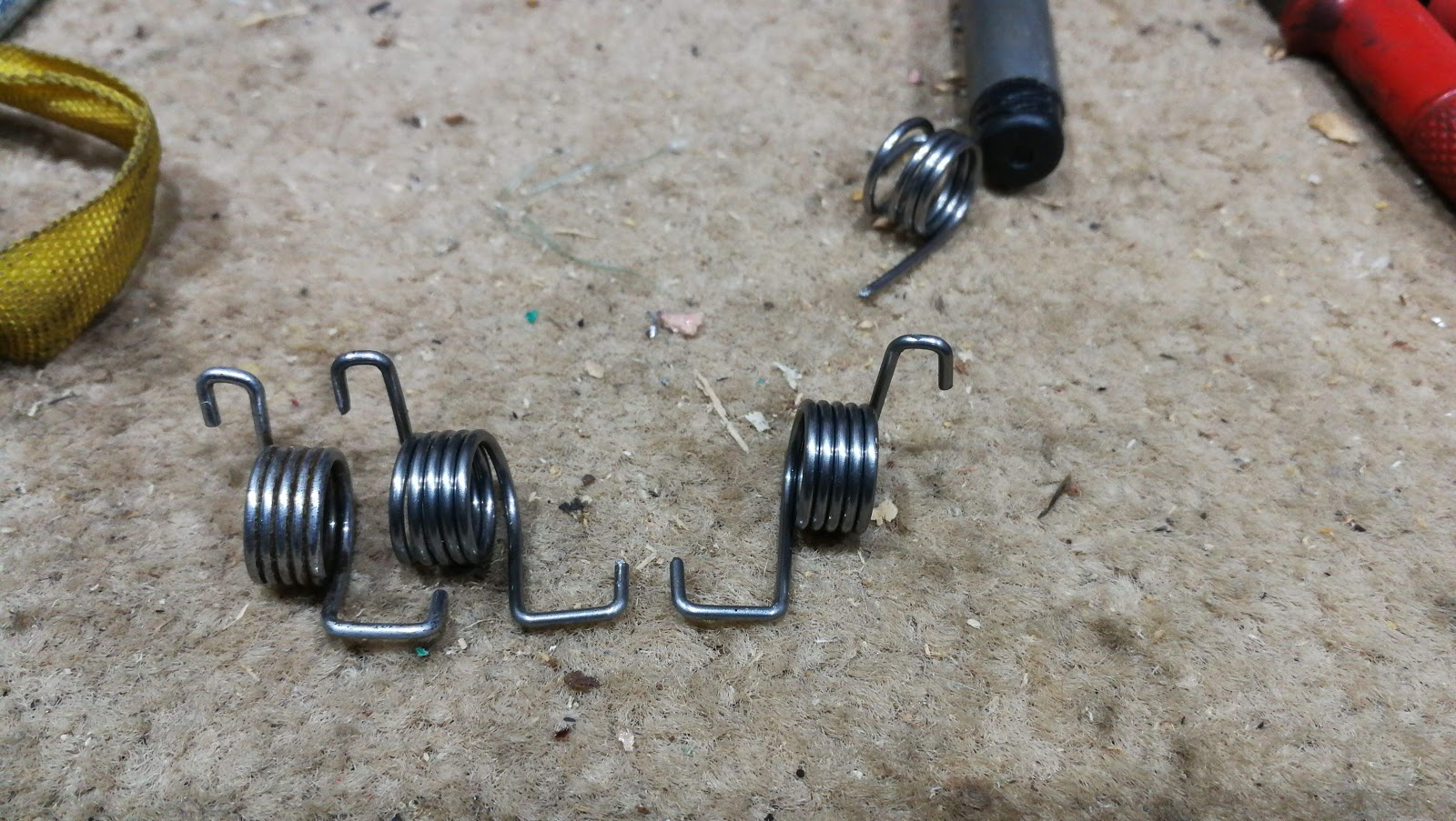
These levers use a special torsion spring wrapped around the lever, which hooks around the lever and bears on the handlebar. The springs are handed, and we have an example:


It's a torsion spring of about 5 turns, with a double bend at each end; I plan to wind a few of these springs, of both hands. I don't plan to plate them; I'll probably paint them black. The plan is to bend one of the right angles into one end, wind the spring and then make the other bends. Whether we can do that without heat remains to be seen, and the spring will need to be tempered to reduce the residual stresses left after the bending operation.

First though, I need to establish some dimensional parameters in order to make the tools to wind the springs. The micrometer shows us the wire is 0.060" diameter in it's plated condition; I was able to buy some 0.055" piano wire easily from eBay.


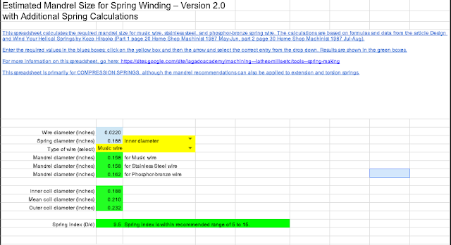
Click the picture to get a link to this calculator. Based upon the number of turns and the wire diameter, the calculator tells me that I need to have a mandrel of 0.344" diameter, which I will turn up on the lathe:


The mandrel will need a 'flag' to trap the first end of the spring, like this:


I've welded this in place:


The flag needs a notch to trap the first end of the spring


You can use the notch to form the first end:


Forming this way does not produce a neat square end like the original.

However, in the interest of learning I made a prototype in the lathe. I turned the lathe in gear, power off using a tommy bar in the chuck key slots. I formed the spring using hand tension only and produced this first spring. the second end was formed with pliers:


Not too shabby; I know that the mandrel is still too large as I planned to avoid taking the finishing cuts until I had welded it so it is no surprise that the spring is slightly too big - I am on the right track though.

In the next few pictures, I show my latest method. Not wishing to put too much time into tooling for two springs, I took short cuts until I could prove the method. If I can successfully and repetitively make these springs, I might make some better tooling.

I folded a bit of 1.5 mm sheet over the wire to make a tensioner. This is notched at the rear so the tension goes into the lathe tool post, and it has a 5 mm hole at the front, so the grub screw retains the tensioner in place without adding to the wire tension; the other three grub screws tension the wire. There is a piece of 6 mm square bar under the tensioner, packing it up. The mandrel is the correct size to the calculator.


From the top down, you can see that I've put a notch in the front of the tensioner. This is to to guide the wire onto the mandrel at the appropriate point.


Here you can see the wire going onto the mandrel:


I think I've cracked the method for bending the springs now. These are bits I've developed:


The first prototypes proved that I needed a better method of forming the bends, as the method of bending with pliers wasn't producing crisp bends. These two pictures show what I did:


So these are the two prototypes I've made, left hand and right hand:


Here's one in situ, showing that the wide end is way too long. It's supposed to fit around that pedestal the the bar is mounted on:


Top Nuts!

I saw these lovely fork top nuts on eBay recently, and had to have them. My SQ4 is not over-restored, it's a patinated working bike but my fork top nuts are very rusty:


These fit the bill beautifully:


I'll need to sort out the washers at some point but for now these look good:


Saturday, 5 January 2019

North Norfolk Jaunt

A few miles in the cold around Norfolk today - Weybourne, Cley and Salthouse on the W/NG:

Moody W/NG Picture

Old machines at Weybourne Beach

Monday, 26 November 2018

More timing gear

In a recent post, we looked at stripping the gear in the inner timing cover. This time, we are going to complete the strip in that area in preparation to splitting the crankcases.

As you will remember, I'd removed the dynamo sprocket after a bit of a struggle and went on to make a gudgeon pin puller so that I could lock the crankshaft, prior to removing the rest of the timing gear.

I locked the crank with a bit of 5/8" bar through the little end eyes, protecting the crankcase mouth with some strips of 3/8" MDF, then I knocked back the tab washers on the oil pump & camshaft nuts.

Both these nuts appear to have a 25/32" hexagon, close to 20mm - I used a 20 mm six sided socket. Fortunately neither nut was particularly tight and they came off with no drama.

The camshaft pinion is provided with two 1/4" BSC tapped holes, so its easy to pull the pinion off:


With the cam pinion out of the way, I could wind off the oil pump drive and remove the oil pump. It's a mazak pump - we'll think about replacing that at some point, but it probably won't be in the first phase of this rebuild. I also took the opportunity to remove the oil pressure relief valve while the cases were still in the engine stand - it's all present and correct, but its full of gunge.


The oil pump drive is damaged - it's old damage, not by me fortunately. We'll have to get it clean to see if it is usable:


I was concerned about pulling the crankshaft pinion off - or rather, I was concerned about spending more time making another puller. In the event, it moved with the slightest encouragement from a pair of screwdrivers.


So that's it for the moment - I just have to clean the parts up, inspect and store them before moving on to the crankcase and crankshaft.

I'll just have a sort through all this sludge...