Showing posts with label oil tank. Show all posts

Monday, 6 July 2026

Model A - more painting

 This isn't very exciting post but it's important to make it to record when these items had their first coats of paint. This Tekaloid takes a long time to dry fully - about 5 weeks - and I want to know when I can assemble bits.

Today I have used the wheel to strip rust and old paint from the battery tray, the rear chain guard, the oil tank and the dynamo chain guard.


They have been degreased, had a coat of primer and their first top coat.


The second coat went on on the 9th of July.


Monday, 27 April 2026

W/NG - a bit of maintenance and a run out

It's a beautiful day in Norfolk and after doing a lot of routine maintenance it's time for a quick run out to warm up the oil prior to changing it. We make a 20 mile round trip to Cromer to do some shopping.

On the way back we stop at home to drop off the contents of the panniers and find something interesting - leaving the bike running on the field stand reveals that it smokes on the field stand - and drips oil from the decompressor.

The reason is obvious when you think about it - the rocker box is drained down the pushrod tubes and on the field stand the whole rocker box is higher on the push rod side and will fill up with more oil than it would when standing vertically. Consequently oil goes down the valve guides and out of the decompressor...


The picture above is the giveaway to this theory - here the bike has been standing outside Morrisons for 10 minutes on the field stand but not running. There's barely a drop of oil on the ground and what there is is on the timing side. It comes from the magneto to chaincase connection I think.

Still, the decompressor shouldn't leak so we'll have to have a look at that yet again. 

I wondered whether the main nut was square to the rocker box and was successfully making a seal there but it appeared that the decompressor body thread was loose enough in the rocker box to accommodate any out-of-flatness. What wasn't so good though was the thread - it's 5/8" BSW but it has an undercut down to something like 9/16", so the 3/8" BSP Dowty washer I was using is way too big. Since I don't have a 9/16" sealing washer, I used a 13 x 1.5 mm O ring and a 5/8" fibre washer - we'll see how that goes whilst we order the correct parts!


Monday, 21 July 2025

SQ4 - back to the road

 A couple of days ago, the Square Four came off the bench to be replaced by the FH in order for me to torque down the cylinder head at 270 miles. The Square rolled easily onto the floor as it's great weight dictates with little left to do than fill the oil  and fuel tanks. 

It had been off the road for something like 4 weeks for a service and one evening I ladled in a gallon of fuel drained from the FH tank. It wasn't until I went to start the engine that I realised the fuel was pouring out of the fuel tap. It had dried out. Choosing the easy solution I soaked it in fuel overnight to see if I could get the cork to swell up again: 

This worked a bit but not well enough. The next day found me replacing the cork with a new one and also replacing the two o-rings in the reserve plunger that I made some years ago. 

Finally getting the engine started revealed another problem - no oil pressure. I ran it for 10 to 15 seconds or so with no success and shut the engine down. I realised that I would have to bleed the feed to the Morgo oil pump. I don't believe I have drained the tank before - the last time I changed the oil I didn't wash the tank out so the oil lines from tank to engine would never have been drained since I built the engine all those years ago. 

Bleeding the pump is very easy as it has a built-in hole for the purpose:

I was pleased to find the timing chest very clean and the sprockets and chain in excellent condition with the tensioner working properly. A few minutes with a screwdriver had oil seeping from the bleed hole and the whole thing sealed up again. 

Restarting the engine found the oil pressure leap up to 50 psi immediately. There is a little niggle here however in that normally the oil pressure will rise to 75 psi on startup from cold, but we do have different oil this time. I'm using Motul 20W-50 in place of the old green tin Duckhams lookalike that I used to buy from Halfords. 

Secondly the engine is not running very cleanly, misfiring a little. There may be some investigation to do.

Monday, 16 June 2025

FH - back in action

 With the Square Four on the bench, the Huntmaster fixed and a trip for a job in Cromer in the offing it's time for a little bike ride. 

In preparation, I topped up the oil a couple of days ago as I had had the return system apart and expected the filter to be empty. I turned the engine over on the kickstarter with the plugs out in order to prove circulation before I used it again. 

After I'd finished my decorating job, I came back to the bike to find a little puddle under the rear chain case. I guessed there might be too much oil in the oil tank and so it proved: 

I filled the big syringe twice getting this back to an acceptable level. It's been off the road for a couple of weeks and obviously wet sumps! 

At the same time I adjusted the front brake and the head race bearings.


Friday, 13 June 2025

SQ4 - changing the oil

 It's high time Square Four had an oil and filter change, so with the oil return line repair complete on the Huntmaster the Square Four is back on the bench after a 10-minute run to warm the engine oil up. 

As usual it's an absolute pig to get the oil tank out but it's very easy to drain the tank and the sump - I have a new sump plate (well, it was new 10 years ago) with a drain bolt and magnet in the middle of it. I had something like 300 ml of oil out of the sump - I'm not sure whether that's unusual or not. 

I was surprised to find the sump strainer damaged - I think I'll get a new one from Draganfly. 

With the oil tank out I can degrease the area around the top of the box where the filler is - it's always quite mucky around here because it's very difficult to top the box up without getting grease everywhere.

The oil tank is also a very tight fit - it's always a struggle to get it out. I'm wondering if it's fouling the frame tube, perhaps stuck between the frame tube and the gearbox plates.

I had the tank in the parts washer for 15 minutes washing the outside and the inside and was pleased to find very little sludge and no debris in the tank at all. There's obviously been some further washing of the engine through the detergent oil that I'm currently using as the cases appear very clean and the goo in the bottom of the tank and on the sump of drain plug is just like the dark grey substance you would get from the crankshaft sludge traps.


You can see one of the cams in this picture - the wear ridge is quite clear. I have a new camshaft ready to go in when I decide that I'm bored enough to rebuild the engine!


I filled in my maintenance spreadsheet but for the record the mileage is 4089 miles.


Wednesday, 8 January 2025

FH - toolbox, charging and other progress

 The toolbox is back on:

In other news, the primary case now has oil and the FERC is no longer dripping oil all over the bench. The oil tank now has a felt wick for the chain case feed:

It's made from a strip of felt, 10 mm x 10 mm x 25 mm:

I made this short video to record the fact that the battery is now charging after we re-polarized the dynamo and updated the RB108:

Doesn't the engine sound great! I got it started a couple of times using Easy-Start, but it only ran for a second or two. Playing around with the fuel supply, I eventually tickled it for a long time - until I had a flood under the carburettor. It started and ran perfectly, but needs choke - perhaps I am starting to learn the technique?

To report on a couple more things: the clutch cover screws are a bit short of thread - there is a 1/16" unthreaded section under the head - cutting the thread on that bit will allow them to go fully home. I've put shake proof washers on them for the moment.

I've failed to improve the front brake - any more turns on the adjuster just lock it solid. It will have to come apart.

The oil banjos on the rocker box are in good shape - they have a lot of contact area though, so they have to be very tight to seal. I've smeared a bit of Wellseal on them which seems to have done the trick.

Number plate next, then the instrument panel and lastly the fuel tank.

Monday, 2 December 2024

FH - little bits

 A short visit to the workshop today got a few little bits done. I've removed the oil tank and fitted a bolt into the seat base above it, and I've tightened up all the seat bolts now so that is secure. Unfortunately in putting the oil tank back I cannot refit all the earth cables - I will have to remove the toolbox again to be able to get to the bolts. I do however have to order the voltage regulator to rebuild the RB108, so that will entail removing the toolbox.


Tidying up the bench I did manage to find the inspection cap for the gearbox so I have given that a bit of a polish on the wheel and refitted it.


I've terminated the HT cables and fitted the plugs so they are ready for first start - so that's oil, sparks, compression and a kickstart. All I have to do now is bolt the carburettor in place properly with some gasket sealant and I will be able to connect up a temporary fuel supply and give it a kick. 

This next bit is the rubber cable tie for the front brake. It doesn't fit properly because my mudguard with its repairs is thicker than was originally intended so what I've done is to increase the width of the groove in this rubber piece, so it should now fit.


The last bit today is just to record that the frame clip behind the oil tank has a new half inch long bolt specially made to complete the fitting of the oil tank.

Sunday, 10 November 2024

FH - more wiring

 Wiring jobs are plodding on at the moment. This next picture shows the splice that I have made to provide a battery feed to the horn and stop switch. It's quite difficult to follow the original wiring diagram and make all of these connections at the battery terminal with modern VRLA batteries with their tiny spade terminals.

It's soldered and covered with heat shrink sleeving.


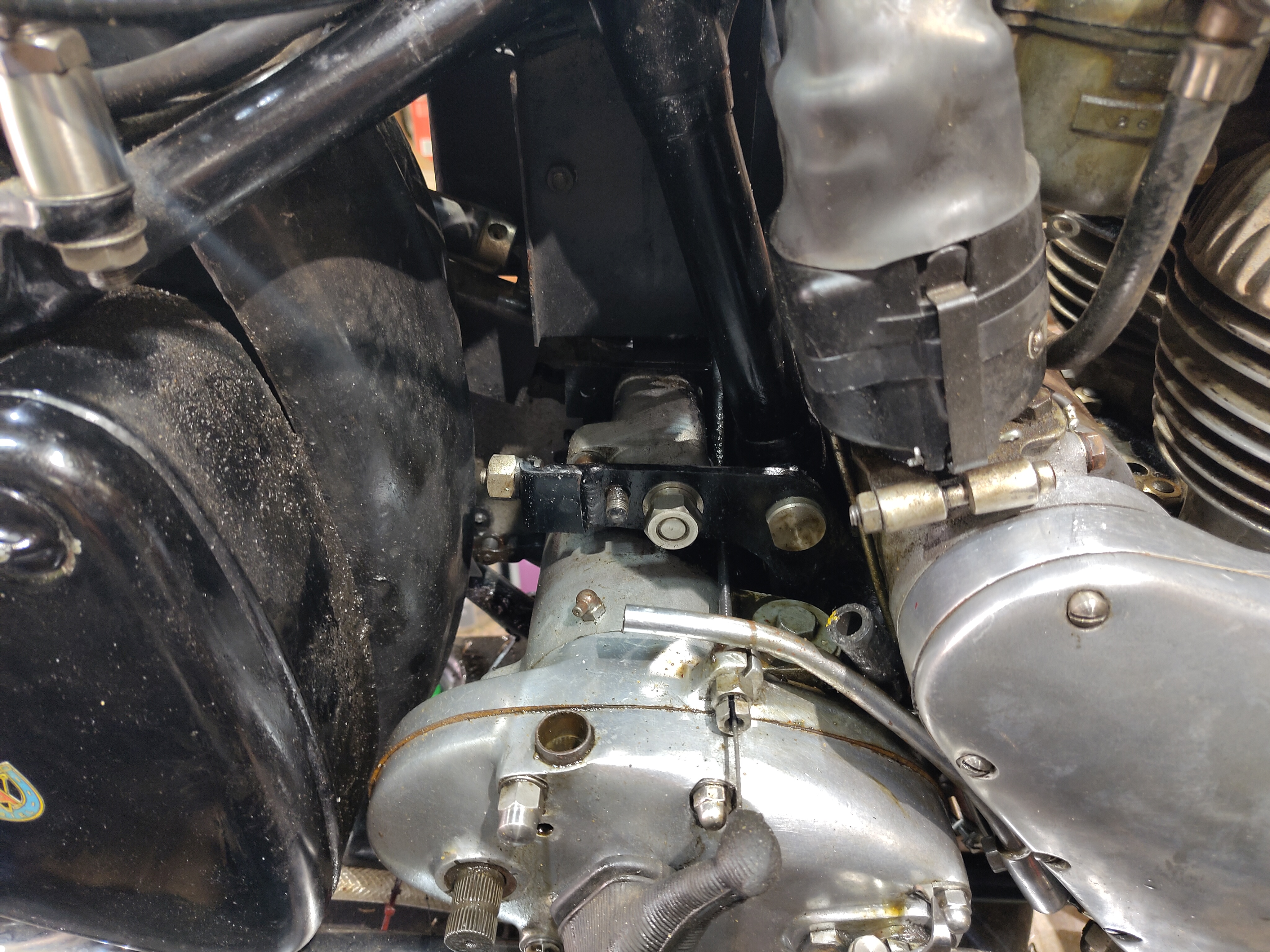
Here is a view of the rear brake light switch. Behind the oil tank, in front of the mudguard and behind the toolbox is a very difficult position to get to to put that bullet connector in. Ariel clearly assembled the switch and the wiring before the oil tank went on - which reminds me, there is no seat bolt above the oil tank, so the tank will have to come off again!


You can also see in this picture that the rocker feed oil line is not very well fitted to the stub on the oil tank. I pushed this on a lot further.

This next one shows the wiring for the regulator, complete with the seal, clamp and split bullets:


That's the battery area complete. For the record, this is wired negative earth which means I will have to flash the dynamo at some point.


For some reason the battery lids are moulded with four cable access slots. This is because they are a copy of the original moulding which had to accommodate large Bakelite knobs for the battery terminals. I've filled two of these holes with black hot-melt glue.


Next stop, wiring up the dynamo. You can see the dynamo D connection on the left, as it connects directly to one of the brushes. The field F connection on the other side connects to one of the white field cables going into the body of the dynamo.

I oiled that felt before I closed the dynamo up.


That's the dynamo wiring sealed up. 


The last job today is to finish the wiring to the rear lamp. These are the finished cables from the harness with Japanese bullet connectors for the stop switch and rear lamp and a crimped and soldered eyelet for the earth.


The earth wire is attached to one of the rear lamp fixing bolts. 


Wednesday, 9 October 2024

FH - hooking up the oil tank

 There's a few jobs knocking around at the moment and it's all starting to get a bit confusing. This next task is aimed at preparing for running the engine up on a power drill to circulate the oil before we put it under any load. 

First off I'll have a look around the oil tank and make sure it's clean and to make sure that I understand the connections - basically that so I don't make a mistake when I'm hooking it up.

Looking inside the filler neck with a camera reveals the return pipe and its hole just above the return strainer.


Next to this on a flat ledge is the restricted hole which leads down to the chain oiler:


Deeper in the tank we can see the feed pipe which is raised above the bottom of the tank, and behind it the drain plug which unsurprisingly is right at the bottom of the tank.


The next step is to finalise the hooking up of the oil lines. These are connected correctly, with the feed pipe on the outside of the tank going to the feed connection at the bottom of the engine.

Next we'll swill out the tank with paraffin, finalise the screwed connections, and make up the push fit hoses for the chain oiler and the rocker box oil feed.

Friday, 3 June 2022

SQ4 - Oil Leak from the Rocker Feed

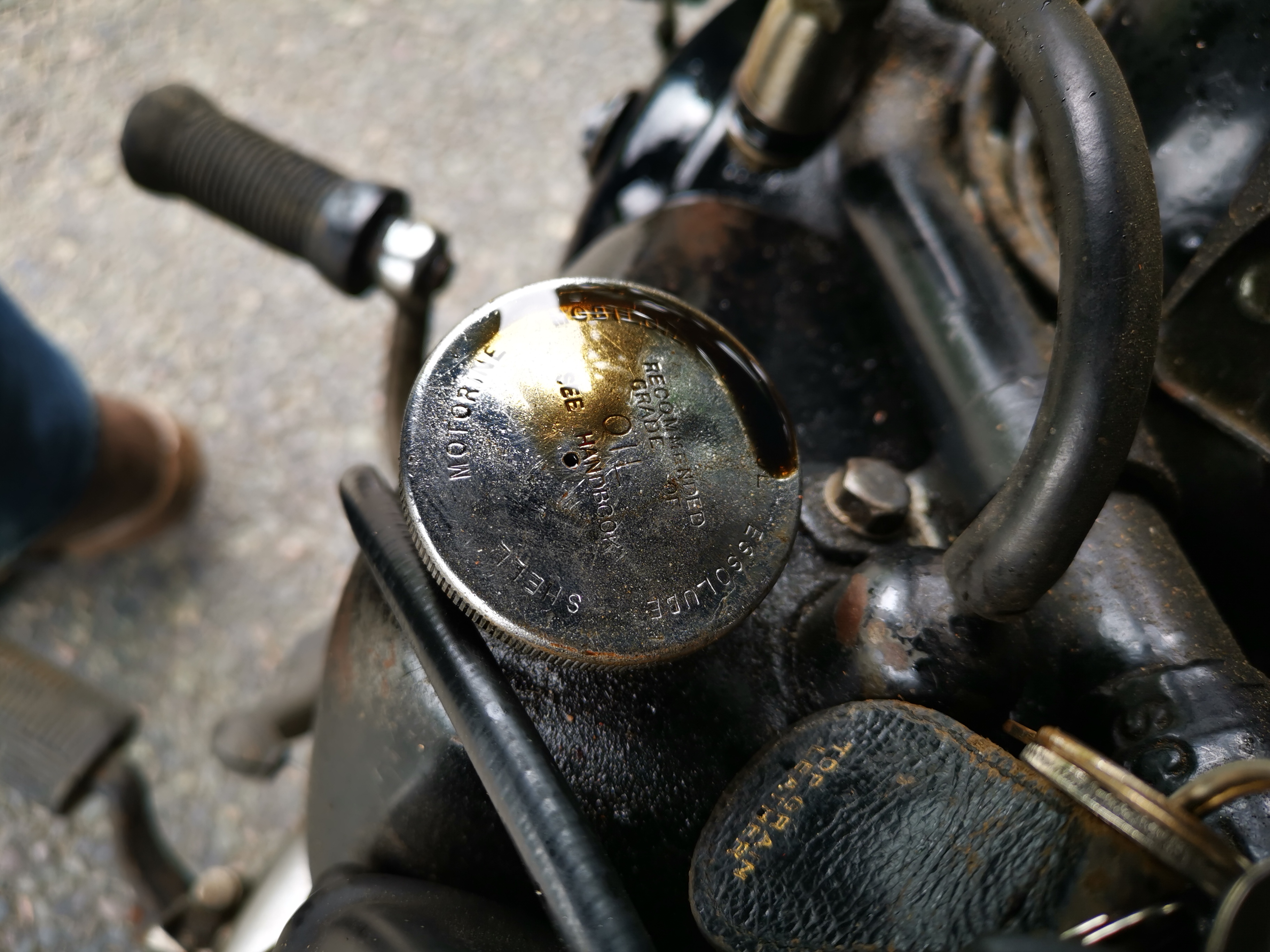
 This may be a seminal moment in the history of my SQ4. For years it's had an oil leak which I have always assumed to be poorly sealed pushrod tunnels at the head joint. However, having addressed a problem with a leak from the oil tank cap, something else which it has always done, I resolved to look at the drip from the rocker feed pipe. 

The oil tank cap has always had a weep from the breather:


Which translates to a wet leg on a long, fast run:

Looking at that first picture, I got to wondering why the cap has a vent hole when the tank has a piped breather that I have taken past the rear wheel. Surely the cap should be sealed?

It turns out that Square Fours don't use the same cap as other Ariels. I noticed that the 1951 SQ4 parts list has a -32 number for the cap - most bikes (other than Square Fours) I've seen use a -29 number. Maybe 5854-32 has no breather hole.

A blob of solder will sort it.

Onto the rocker feed. I ran the engine cold (75 psi on the gauge) and as the oil warmed up the leak appeared:

Now, my bad - I forgot to take a camera to the workshop when I fixed it. It turned out the tube was not pushed into the fitting at all - it was just held in place with a fillet of solder at one end, and had been like that for years - probably eight years. It's been leaking for most of that.

All fixed now.

Thursday, 30 April 2020

FH Dry Build - Fitting & Repairing the Rear Mudguard

Updated: first published 27th April 2019

The whole point of a dry build is to trial fit parts before committing to an expensive paint finish that you might ruin with any remedial work you have to do, and the rear mudguard was a good example. Aside from the moth damage at the join, the mudguard wouldn't fit with the oil tank in place.


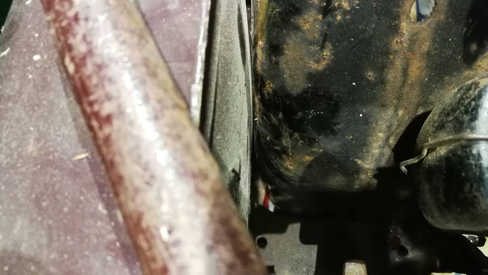
You can see the back of the oil tank bulges and pushes the mudguard to the nearside:


The centre bolt won't line up:


And here is the problem - the back of the oil tank is supposed to be flat:


Five minutes with a dead blow hammer, working around the edges has it back in shape. There is clearance between the back of the oil tank and the mudguard now, and the mudguard's centre bolt is in place.


Having got the mudguard to fit, we now need to repair it. It's not the worst I've seen.

This is the rear end of the main section showing the rust damage to the bridging piece, to which the tail section is bolted:


This is what it is supposed to look like:


And here is the front end of the tail section:


Again, this is what it is supposed to look like:


I cleaned this up with a wire brush a while ago to get an idea of what I was going to be dealing with - those holes are in the main blade section as well as this joining panel. Notice how the joddle that lives in the mudguard rib is rather deformed - it's flattened toward the rear end. It's quite square at the front and is clearly supposed to fit inside the rib, with the rear light cable below it - the cable does not go between the mudguard and the joining rib. We'll need to remove that, make a new one, and repair the guard as well.


Here's the blank, sliced from a quarter sheet of 20 SWG CRS. It's 3" wide and about 15" long.


Here it s again, with a datum edge trued up on the linisher. It's marked out with a Sharpie against the dimensions of the old, moth-eaten one.


Here are the first two bends going in:


And joddling the top hat section in the middle:


Next step is to fold the two lower channels that fit around the rolled edge of the mudguard, then we will make the main bends. When that fits, we will cut out the old one and repair the main blade.


Here's the first bend of the two side channels:


To make the next bend, the work has been inverted from the previous shot, and it is clamped to one of the folding bars using a piece of 25 x 4mm flat bar. The second folding bar has been raised by the depth of the bend:


Here the work has been folded down over the raised folding bar, producing a joddle:


And here, the joddled section has been clamped behind a 1/2" bar and bent again, producing a shallow channel:


That done, we joddle the last bend and repeat the whole process at the other end to produce this.


I'm very pleased that it sits flat on the bench, with it's datum edge remaining straight and proving that all the bends are square.

Next we need to make the curves, and for that we need a former which is where this empty gas bottle comes in. These were a very expensive way to buy Argon that I used to use before I rented a refillable bottle:


A line drawn parallel to the axis of the bottle, and another square to the datum edge ensures the bend is square:


Easy.


And it even fits. The marker line you see in the holes is drawn 1/2" from the datum udge, copying the hole positions from the original:


I've drilled the top two holes 9/32", to clear 1/4" screws which we will use for the next steps. These screws will ultimately be 3/8" (for my 5/16" threaded bobbin), but drilling them smaller allows me to move them a little if I need to. The bobbins look like this:


Having a quick look at the side pieces and the holes reveals I have been generous with the length of the blank, and the rolled edges of the tailpiece prevent the over-long bridging piece sitting in the correct position.


The next job therefore is to cut away the old bridging piece from the front section of the mudguard, so we can edge a bit closer to having the bridging piece in the right place and trimming it up. The old one was not too difficult to remove as it was extremely weak; I could see where a couple of the spot welds were and I removed these with a special spot-weld cutter which has been knocking around in my sheet-metal toolbox for decades:


It's a small, double ended saw blade (imagine a 5/16" hole saw) mounted on a mandrel. You can cut right around the weld:


Here's the end of the front section with the bridging piece mostly gone:


I'm going to cut it away back to that black line and let in a new piece of steel, like this:


I'm very happy that I've finally found a decent bi-metal blade for the bandsaw, as it makes life very easy when you want to cut out bits of sheet. This is the new panel - I used a similar technique to before for the centre rib; the curves are bent by hand:


Tacking up. I have a narrow dart in either side to let the new panel curvature match the old guard:


And here is the joining piece, with similar darts. Here it is bolted to the rear section:


These are skin pins - I have about 15 of these 3/16" pins, used for holding sheet metal parts together before welding:


Here's a couple of pictures of the mudguard bolted up:


From the inside, the bridging piece is approaching the final shape. We need to machine the weld nuts on the lathe and get those in next.


This view shows the mudguard with the bobbins in place and bolted up. I made them 1/4" BSC, to give myself a bit more wiggle room. I may make up some special 1/4" bolts with 5/16" size heads, domed and polished.


Here is the bridge piece again, held in place with a few skin pins and with the rear section bolted in place with 1/4" BSC bolts. This all looks good and the bobbins & bolt holes all align, so we can weld the bobbins in place:


Leaving the skin pins in, we can start closing the various joints. Secondly, one at a time, we remove the skin pins and make a plug weld in the hole, which fastens the bridge piece permanently to the main section of the mudguard:


Turning our attention to the other half of the mudguard, we draw around the mangled ears onto a small piece of 20 SWG, and cut it out with snips and the band saw. I've left  14 - 5/16" edge to allow for turning over:


We can raise the edge using various forms - lifting the whole edge gradually to avoid unwanted stretching:


Eventually we can raise it to 45 degrees - and then the end can be beaten flat.


We need two of those, one LH, one RH. We'll use the snips and a hacksaw to remove the old ears:


We need to be very tidy about this, so the new piece fits in the right place:


Welding against old metal is often tricky, but this has gone surprisingly well. Not so neat, mainly due to the fact that I dipped the tungsten in the weld pool part way through...


And the other side - there are four holes to fill, two holes to drill and then we are done:


I'm not sure what these two holes were for - a rack perhaps. To repair them, first clean the area thoroughly:


I tack a little patch on the back - this will be ground off eventually:


Fill the hole from the outside:


We'll grind it flat in a bit. We can do the same with this one: