Showing posts with label GB. Show all posts

Monday, 9 December 2024

FH - head steadies

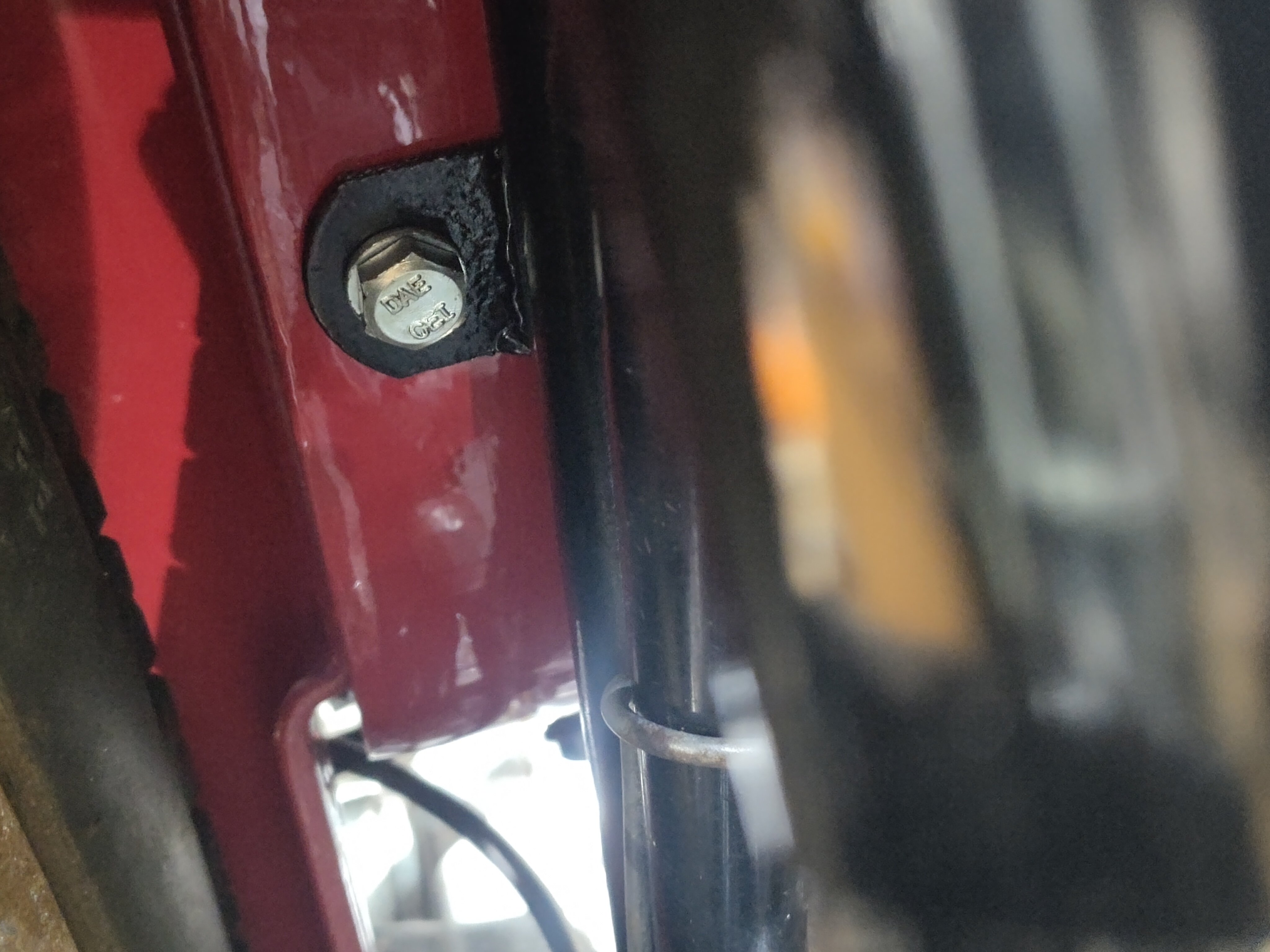
 A couple of hours in the workshop yesterday saw a few little jobs closed off. This was the worst:


Access is not easy, but the secret is a short open spanner.

The head steadies are now fitted with full size 5/16" nuts, which entailed lifting the rocker box (twice) to get them in.

Next up was the timing side footrest, which wasn't fully tightened up - doing that enabled the exhaust fitting to be completed on that side, with the exception of the finned clamp.

I fitted the speedo cable, to find that the locating pin in the gearbox was missing. The AOMCC gearbox man has them available.

I spent a while poking around under the instrument panel, where the ammeter has lifted out of the position and the cable routing is poor:


I've almost fixed these problems, but the ammeter is still out of position and the wire from the lighting switch to the dipswitch is too short; the feed from the ammeter to the indicator relay is badly routed and consequently too short, and the indicator relay terminals are almost impossible to reach.

The instrument panel is going to have to come off again.

Monday, 2 December 2024

FH - little bits

 A short visit to the workshop today got a few little bits done. I've removed the oil tank and fitted a bolt into the seat base above it, and I've tightened up all the seat bolts now so that is secure. Unfortunately in putting the oil tank back I cannot refit all the earth cables - I will have to remove the toolbox again to be able to get to the bolts. I do however have to order the voltage regulator to rebuild the RB108, so that will entail removing the toolbox.


Tidying up the bench I did manage to find the inspection cap for the gearbox so I have given that a bit of a polish on the wheel and refitted it.


I've terminated the HT cables and fitted the plugs so they are ready for first start - so that's oil, sparks, compression and a kickstart. All I have to do now is bolt the carburettor in place properly with some gasket sealant and I will be able to connect up a temporary fuel supply and give it a kick. 

This next bit is the rubber cable tie for the front brake. It doesn't fit properly because my mudguard with its repairs is thicker than was originally intended so what I've done is to increase the width of the groove in this rubber piece, so it should now fit.


The last bit today is just to record that the frame clip behind the oil tank has a new half inch long bolt specially made to complete the fitting of the oil tank.

Sunday, 1 December 2024

FH - replacing the kickstart cover

 We are inching ever closer to starting the engine now; the timing case screws have all been cleaned out (and shuffled around in some cases - the 'medium' and 'long' screws are only 1/8" different and a couple were mixed up) so we need to get the gearbox together.

For the record, the rather mangled mainshaft tab washer is bent up against the flats and the 5/16" ball is fitted with the correct pushrod and mushroom, lubricated with Morris K400EP:

The kickstart cover components are assembled, though in this shot the spring is not tensioned:


Here we have the levers fitted, spring tensioned and the levers wired together:


The next step was to turn the cover over and apply some Wellseal to the gasket face. I stuck the gasket to the Wellseal, and applied some more to the gasket. Because I'm using oil in the gearbox, I'm going to ensure that there is some grease around the main leak path which is the speedo drive in the bottom of the kickstart case. I've applied some Morris K400EP to that area slapping it in all around the gears before fitting the outer kickstart case. 

There's no pictures because this is a bit of a two-handed activity but suffice to say the gearbox cover went on very easily - much more easily than is typical with a BA or CP gearbox. In this next picture it's all screwed down with the new Acme stainless steel screws. 


It's looking great and I'm very pleased, though I'm a little bit concerned that the kickstart spring needs another turn.


Tuesday, 8 October 2024

FH - gearbox

 First off let me just say that I'm not going to rebuild the GB gearbox on the Huntmaster just yet. The gears select well, there's no play in the mainshaft, no lateral play in the gearbox as far as I can tell and whilst there's a little bit of movement in the sleeve gear it's no worse than other gearboxes I've looked at at the outset. Turning the shaft by hand doesn't reveal any strange noises so I think we'll just leave it be for the moment. 

However, there is something strange going on. When I assembled the clutch I discovered that I couldn't get the plates to touch, even when the screws were done up relatively tightly against the springs which made me think that perhaps there were two ball bearings within the main shaft. I fitted a new one when I replaced the push rod but now that the pushrod assembly is effectively over long I think there may be two. 


Of course I can't remove the ball bearings from the clutch side because they are right down at the other end of the mainshaft and I've no means of pulling them out. Therefore I've got to remove the kickstart case cover, have a look at the clutch mechanism and remove the balls from that end. This will give me a chance to polish the kickstart case cover to match the timing cover. Secondly it will give me a chance to look at the mainshaft end float and to learn a little bit about the gear selector mechanism on the GB, which I've never looked at before.

The kickstart quadrant is in lovely condition:


It looks very clean inside and it's immediately obvious that the design is a little more sophisticated than the BA/CP type that I'm used to. The mainshaft has no detectable end float that I can find. It's obvious that the gearbox has only had oil in it; though I will probably use the Morris K400EP grease in it as usual.


Moving the pushrod from the clutch side, having pulled the lifting mushroom out revealed something rather strange. There's a large lump of what appears to be oily rust sitting at the end of the main shaft:


I pushed this out and then ran a little roll of paper up and down the inside of the mainshaft swabbing out the remaining muck. It was at this point that I realised that the quarter inch push rod that I had made in a previous post is the wrong diameter for the GB gearbox. Speaking to the various members of the club, including the gearbox specialist, revealed that GB gearboxes use a 5/16" diameter push rod. 

While waiting for some new bits to arrive I'll polish the end cover:

Wednesday, 21 February 2024

SQ4 gearbox rebuild

 Now we know what we have to do, we can get started with the rebuild helped by these lovely new bushes from Geoff at AOMCC Gearbox Spares

First job is to remove the two Welch plugs over the layshaft and camshaft; I drill a hole in these and lever them out:


With some heat in the casting, you can drift the layshaft and camshaft bushes out from the drive side:


The sleeve gear bushes come out with a bit of tube; the new ones go in with a large flat drift. They go in quite easily with a hammer (you don't hit the bush directly), but it's times like this that I wish I had a press.


The new drive side bushes can be pulled in with suitable studs and washers:


You need to be careful with the layshaft bush. It's easy to get it misaligned, and there is an anti rotation pin designed to keep the grease groove at the top. At the factory this was drilled and fitted from the drive side, but with a replacement bush you must align the slot in the bush when you put it in.


All this work culminated in 0.13 mm end float (5 thou) on the layshaft. That's better than the 9 thou I had earlier, and I have the proper gasket fitted now.


What's not so good is the 0.37 mm I have on the camshaft. That's about 15 thou and will have to be sorted with shims.


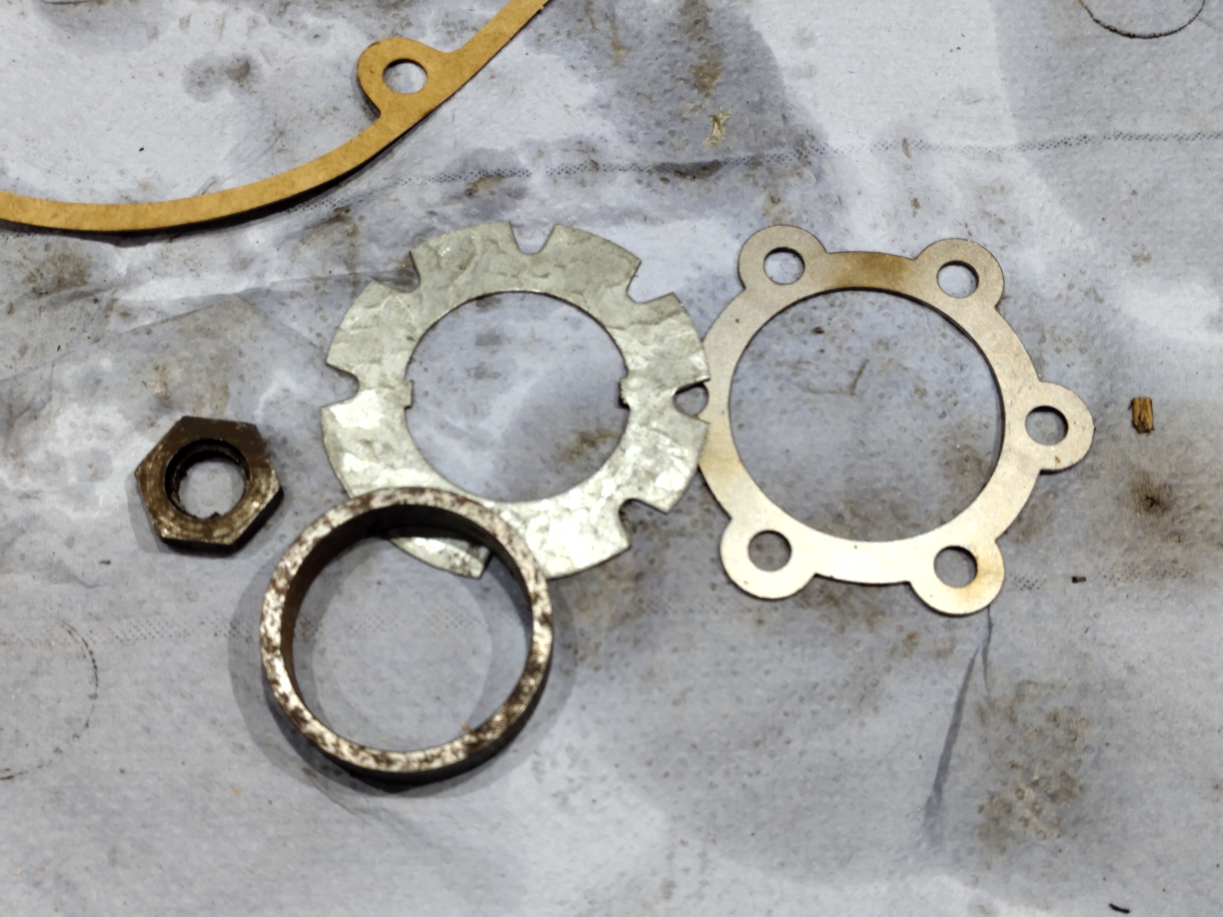
I've also decided to discard these two nuts and make some new ones. The threads are poor and the nuts would be better twice that thickness.


We'll fix the camshaft end float with this 0.3 mm shim. It's a commercially available 26 mm ID shim that I've opened out to fit:


This shim fits inside the inner cover. Unfortunately, I found out later that this is a 0.5 mm shim in a wrongly-labelled bag - testing revealed a selector shaft that was firmly clamped in place.


Here's the selector shaft assembled and greased ready to go in.

A trial fit, with shakeproof washers under the BSW nuts (to prevent them coming loose) revealed the shim problem. I went through two bags of shims with a micrometer and found that all the shims in the 0.5 mm bag were 0.3 mm and all the ones in the 0.3 mm bag were 0.5 mm...

Easily found and fixed, fortunately. It pays to measure and test at every step. 

With that fixed and the selector shaft showing about 0.05 - 0.07 mm (2 thou or so) end float we can set up to measure the mainshaft and sleeve gear end floats.

The mainshaft endfloat still measures 0.88 mm or 35 thou: not surprising, since we haven't changed anything.

The sleeve gear shows 1.11 mm when in top gear:


A call to AOMCC gearbox guru Geoff suggested I make a spacer to reduce that to 0.11 mm, 4 thou, to maximise spline engagement. Geoff provided a useful spacer to make that from:

This is the spacer that sits under the gearbox sprocket, inside the oil seal. It parts off quite easily on the mini-lathe, once you remember that you don't want the lathe in high gear!


The spacer fits neatly on the inside of the main sleeve gear bearing, pushing the sleeve gear splines into further engagement with the mainshaft sliding gear splines.


To deal with the excess mainshaft end float, I have machined a 0.5 mm recess into the mating side of the nut. This will restrict mainshaft travel a little more and should bring the end float down to somewhere near 0.38 mm, or about 1/64".


Reassembling the gearbox reveals sleeve gear movement at 0.8 mm; I must have measured that wrongly as I thought I had 1.11 mm and added a 0.75 mm spacer. Mainshaft end float is now 0.6 mm, down from 0.88 mm and around 25 thou. This is 1/40", within Ariel's stipulated range of 1/64" - 1/32".

All good news; however, since tightening the inner case nuts for what I thought was the last time, I've realised that the camshaft is too tight. It turns, but that 2 thou end float has clearly been taken up by gasket compression - I may relieve the bush a little or I may fit shims to 0.2 mm (8 thou) rather than the 0.3 mm currently fitted (12 thou) which should give me what I need.

As it turned out, smoothing the surface of the camshaft bush was all that was required to return to normal operation, so I tightened up the end cover. The last step was to fit the two Welch plugs, which have to be done before the sprocket goes on for the last time. It would have paid to ensure the bores for these were clean before the bushes went in, as enthusiastic staking at the factory had left a lot of material in the layshaft bush bore which had to be scraped out with a twist drill ground flat, like an end mill.


Next job is to close up the other end of the gearbox, but I can't do that without the clutch in place as I can't hold the mainshaft to do the nut up on my own.


More next time.

Friday, 2 February 2024

SQ4 Gearbox Investigation

Starting the Square Four up mid winter is something I do at least once a week just to make sure it's all working, which it usually is - except when it isn't.

This week I was met with an unexpected noise, like gear-dogs clashing - it sounds like it does when you put it into first gear. Listen to the sound, especially obvious around 28 seconds:


The noise stops as you disengage the clutch (which is dragging badly) as the mainshaft slows to a stop. It's also not present if you run the bike in gear on the rear stand.

Casting to the forum & FB world for advice, I ended up having a chat with AOMCC gearbox guru Geoff - 30 minutes of good advice. To summarise:

  • Poor Sleeve gear position leads to dropping out of top gear. It seems I might need an extra spacer to move the sleeve gear towards the mainshaft sliding gear
  • Minimise Layshaft end float, centralise in new bushes
  • Minimise Camshaft end float
  • All the bits are available from AOMCC Gearbox Spares, no bushes need reaming 
Here's the gearbox drawing, for reference:


So on with the work; first job is to get the bike on the lift. This entailed fitting the centre stand springs to the FH, which is a story in itself. Having the half-built FH on the bench is quite a different experience to having the SQ4 up there - you realise how heavy it is, but the lift is quite happy and accommodates the rear stand quite well.


Yet again the bench proves it's worth, supplemented by the new lights overhead. I bought some strip lights to add to the interior light circuit, and when I put them up I moved the old interior lights, which used to face the benches, to face the bike on the lift. Then benches are taken care of by their own circuit, and now I have both sides of the bike illuminated.

Removing the outer cover reveals no issues with the selector or kickstart. I must remember that this box is missing it's kickstart rebound rubber if I recall correctly.


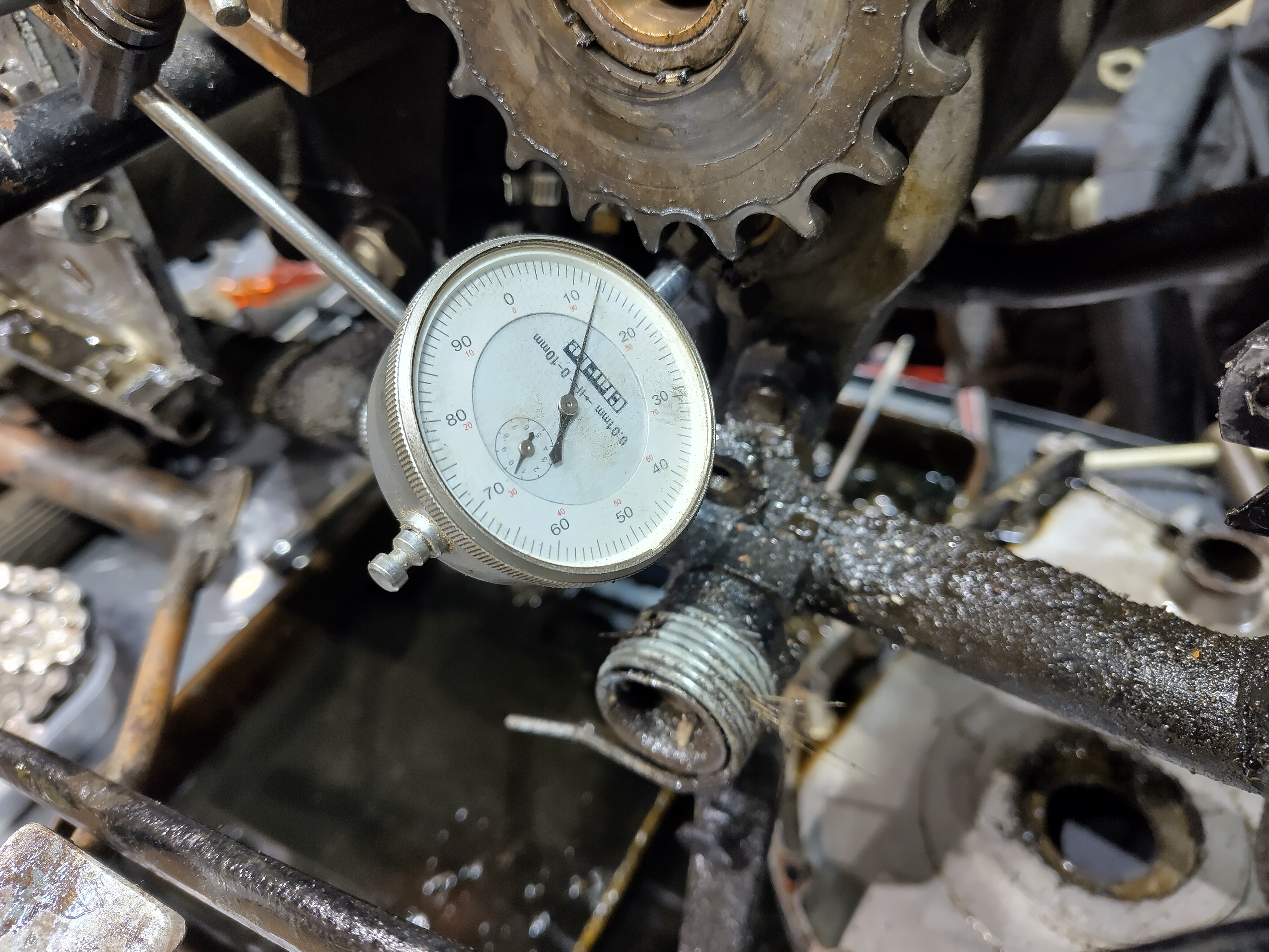
I set up the DTI on the lift deck. This isn't ideal, as it reveals the bike is swaying about a little on it's stand but the arrangement serves to reveal 1 mm end float on the mainshaft, 0.3 mm on the layshaft and 0.3 mm on the selector shaft. The limit specified in Waller for the mainshaft is 1/32", which is about 0.8 mm. There's nothing specified for the other two shafts.


You might recall some issues we were having with the clutch towards the end of last season - I wrote them up here in a post called Clutch Investigation. The end float in the mainshaft possibly contributed towards this problem.

We'll move to the other side now; the first discovery is no surprise - the clutch centre nut has backed off again, though the tab washer prevents it moving too far. The reason for this is the splines, which are very worn and won't take any load without moving a little:


This is a new AOMCC clutch centre. The splines are wider and have square shoulders:


With the clutch off, I was able to get a better quality mainshaft endfloat measurement of 0.88 mm (35 thou) with the DTI magnetic base mounted on the engine/gearbox plate


Moving the DTI to a steel plate clamped to the gearbox produced some better numbers for the layshaft and camshaft:


In summary, I have end floats as follows:
  • 35 thou on the mainshaft, a bit over 1/32”. Ariel's stated limits are 1/64" - 1/32"
  • 9 thou on the layshaft. Ariel only state a minimum for this end float.
  • 9-10 thou on the selector. Ariel only state a minimum for this end float.
So, barring the sleeve gear, I have it all apart and can measure up. The parts washer is such a useful piece of equipment.


In no particular order, here are some pictures. Having stripped the gearbox I have discussed it with various experts on the AOMCC forum and Facebook pages, and twice with Geoff, the AOMCC gearbox spares specialist. These are the two selector pins - the wear is obvious, but not measurable. These are not going to be changed.
 

This is layshaft 2nd; dogs are good, teeth are good.


This is the layshaft sliding 'clutch' - dogs are good, splines are good.


This is mainshaft 3rd; dogs are good, teeth are good.


Selector forks are a little worn but show no sign of bending, burning or major damage. They are a good fit in the grooves on the sliding sleeves.


Two things in this picture - the sleeve gear, which I can't remove yet (big box spanner on the way) and the drive side layshaft bush. The shiny ring shows you where the layshaft output gear has passed it's end load.


The dimensional survey revealed the following: 
  • Layshaft 2nd gear bush 1.061” gear 1.065” 4 thou clearance
  • Layshaft 1st gear bush 1.062” gear 1.0653” 3.3 thou clearance
  • Mainshaft 3rd shaft journal 0.786” gear 0.788” 2 thou clearance
  • Sleeve gear bearings: 
    • Mainshaft outer journal 0.931” sleeve gear bush 0.940” 9 thou clearance
    • Mainshaft inner  journal 0.928” sleeve gear bush 0.941” 13 thou clearance
  • Kickstart pawl bush length 0.81”
  • Layshaft timing side bush 0.663” shaft journal 0.652”, 11 thou clearance
  • For some reason I didn't record the dimensions of the layshaft drive side bush or the camshaft bush, but I guess I had already committed to changing them because of the end float. Well, that's the best excuse I have right now.
And another one from the experts - it looks like the timing side mainshaft nut is wrong, as it doesn't bear on the kickstart pawl at all.

So that's it! New layshaft, camshaft and sleeve gear bearings and a new kickstart rebound rubber.