
Showing posts with label fuel. Show all posts

Friday, 22 March 2019

Charlie's Shed - Fuel Tap Plungers

If you find yourself short of plungers, or the shaft of your adjustable plunger is damaged, they are quite easily made if you have access to a lathe.

The brass centre of the adjustable plungers, which is often short from having the slotted end broken, can be made from a bit of 3/8" round bar. Chuck this in the lathe and turn a suitable length to 5/32" - the best way to do this is to turn an 1/8" or so to exactly the right diameter, then use this short length as a guide to turn the rest in one pass. With a sharp tool this shouldn't be too much of a problem and it avoids the tiny bar bending away from the tool, which will result in the outside diameter being over size.


Chamfer the end and cut the thread - it's 5/32" BSW. Make sure you use a tailstock die holder or back the die holder up with the tailstock to keep it square - you don't want that thread wandering off.


Give it a polish and part it off:


Assemble it into the plunger and you are done:


The shaft I have made here is a bit over-length compared to the old one - maybe I will adjust it a tad. Notice the diamond knurl. I don't have the cutters for that - straight and diagonal knurls yes, but not the 'inverted' diamond knurl. Rather nice, and easier on the hands...

Post war plungers, as I mentioned in my other post on the subject, are non-adjustable unlike their prewar forefathers, and because of this I think it makes sense to update them with an O-ring seal.

The hexagon reserve plungers are made from 0.600" 303 stainless steel hexagon bar. You'll need a decent length for chucking and for the milling operation. Chuck the bar with a couple of diameters showing beyond the jaws, to give you enough space to part off when you are done:


Turn the shank to the required diameter - a little over 5/16". This needs to be a loosish clearance fit in the tap body you just reamed.


Use a thin parting tool to form the O ring grooves. Space them so that they are at either end of the equivalent length of cork:


For those, like me, without a mill you can use the toolpost or a milling attachment to mill a 3/32" slot, about 1/16" deep in the tap shank. Since the loads involved in this operation are tiny, I didn't bother to set the lathe up for milling. I cut the slot at about 1500 rpm in two passes, with a 3/32" slot drill.


Once you have completed the milling, test the plunger in the body and make sure the plunger slides freely with the retaining screw in place. Next, put the bar back in the chuck and polish up the shank; then, before you part off, turn the shallow chamfer on the inside of the head. You can then part off.

Turn the plunger in the chuck, and skim the outside face of the head, cutting the shallow chamfer in the same setting. Polish the head and you are done.
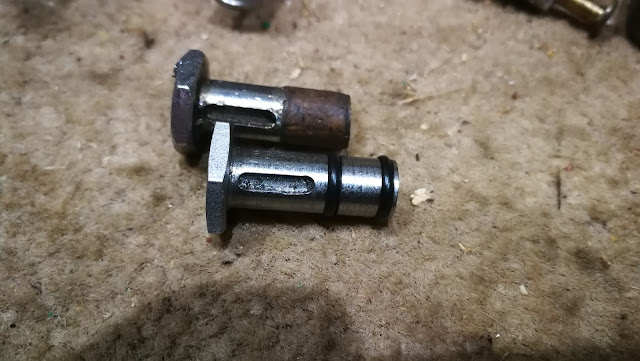

And watch out - the reason that slot looks slightly ragged is because I broke a cutter in it. Go easy.

Next thing - you will want to smooth the edge of the ports in the tap. look at this:


See the sharp edges? Remove that with a burr in the Dremel, or a tiny grinding tool. If you leave it, the O ring will be damaged. Look:


That nick will cause a leak. You are not really supposed to use O rings in dynamic applications like this.

Thanks for reading, and I hope you found it useful.

Sunday, 17 March 2019

Charlie's Shed - Fuel Tap Leaks

Updated from 2017

Following on from the replacement fuel filter I made here, I wanted to show you how I have renovated the double plunger taps fitted to my Ariels.

The plungers fitted to these taps are a simple design with a few variations - prewar, the plungers are adjustable and of about 3/4" diameter; post war, they reduce to about 5/8" and lose their adjustability. There is the plated knob, which may be round and knurled or hexagonal; the knob has a short shaft which has a milled groove, aligning with a peg in the tap body (to stop it coming out), and this groove is usually straight, but may be milled with a dog leg such that you can turn the knob to avoid inadvertently shutting off the tap. Fitted inside the knob is a brass inner shaft, of about 5/32" diameter for most of its length which is provided with a short section of larger diameter, to fit inside the tap body and to carry the cork.

Lastly there is the cork - a cylinder shape fitting tightly inside the tap body and around the inner shaft.

Here's a selection. These are all post war (so about 5/8" diameter; the hex is 0.600" across flats), and came to me from John Mitchell of the AOMCC.


You'll notice how some of these plungers have a straight slot for the retaining screw, and some have a slot with a 90 degree bend. These are the 'turn to lock' type, which are later than the ones with the straight slot:


Now, these taps are pretty reliable if you know what you are doing when you set them up. The corks wear, and they dry out leading to leakage but if you keep them in good condition they work well. If you have a leaky tap, first consider what you have been doing with the bike. If for example you drained the tank over winter, or the bike has been out of service for a while, or you just bought the tap off eBay try letting the plunger soak in a puddle of petrol for a while, or immerse it in a pot of boiling water for a few minutes to rejuvenate the cork. This approach has restored many taps to working order.

If you have to replace the corks, you need to remove the inner shaft using a punch - a 3 mm or 1/8" punch will be fine. Locate the mushroomed end of the inner shaft and place the knob, shaft down, in the jaws of a vice.


Tap the mushroomed end of the inner shaft with your punch and drive it out


You should have the plunger in two pieces:


Replace the cork. Check that the new cork has a hole that is on-centre all the way through, and that the ends are square - a lot of them are poor quality. Check that it is solid and does not have any dark grooves in the cork that are going to cause leaks.

Check also that it is the right length. The short length of MIG wire in the picture below has two bends in it - one to indicate the open end of the tap and one to indicate the location of the fuel port drilled through the tap - the port that the cork will shut off. You can see that the short cork fitted to the tap has no hope of covering up the holes, but the longer new cork will cover the holes nicely.


Reassembly is simple - fit the new cork over the inner shaft and press the tap together in the vice. Wet the cork in petrol and try it in a tap - it should slide but be quite stiff. Up end the plunger again, and use your punch with a hammer to slightly swell the small end of the inner shaft, retaining it in the tap.

Prewar, the tap plungers were made so that you could adjust the corks and the reassembly sequence is a bit different. This is a prewar plunger, though not in it's own tap; the inner shaft has a 5/32" BSW thread (yes, really) retaining it in the knob, and the hex is about 3/4" across flats.


The shaft has a screwdriver slot and a lock nut, so when you slacken the lock nut you can turn the shaft and knob independently and compress the cork, improving the seal. The lock nuts are often missing, but early Meccano nuts are identical and readily available from specialists; they are a 5/32 BSW thread, but the hex is designed (or maybe just fits) 4 BA spanners.

The shafts are sometimes too short - the screwdriver slot is easily broken if you try to adjust it without removing the locknut. In this case, the only option is to replace the shaft or the whole plunger. Replacement shafts are not available but can be made on the lathe, as I show in this post.

There is a note of caution here though. If the locknut is absent, the thread damaged or just not tight, my W/NG is perfectly capable of loosening the tap cork after a fast run. The result of this discrete self-destruction is a strong smell of petrol in the garage and a drip tray curiously full... The moral of the tale of course, like most things with old bikes, is that nothing is 'fit and forget'.

If after replacing or adjusting your plungers, your tap is still leaking there maybe excessive wear or damage to the tap bore; you may have had trouble adjusting the cork to get it to slide evenly. It's a good idea to remove both plungers and inspect the bore - if you suspect it is worn, run an adjustable reamer through it to skim the surface and restore a consistent diameter through the tap. The bore is normally about 11/32" ID - I use an 11/32" - 3/8" adjustable reamer. Your aim is to remove the minimum amount of material, but to true up the surface:


When you have passed it through, look and see if you have cleaned the whole surface of the bore:


But what if you have no plungers? If you have a lathe you can make them quite easily, as I show in this post. Indian-made plungers are readily available on eBay and the ones I have seen use long M4 screws for the inner shaft. These are again of highly variable quality - the ones I have are plated very well, and look good - but of the five I have, only three have the inner shaft hole in the centre and the corks are way too short...


Usefully though, they can also be made adjustable. I made this one using a long brass M4 screw, with a slotted head filed flat and an M4 lock nut.


Once refurbished, these taps are very reliable. Attach them to the tank with a Dowty sealing washer:


Here's a dual plunger tap beloved of Ariel, fitted with two pre-war (so large size), adjustable plungers.

Saturday, 7 July 2018

Shields Up, Mr. Scott...

In the everlasting challenge to keep heat away from my carburetter, I have added a heat shield to the previous insulating gasket.

I know from test rides that the radiated heat from the engine is as significant as the conducted heat, so I have attempted to deal with that with a stainless steel heat shield, mounted on the front float bowl screw. Petrol boils at 95 C, and we have seen temperatures in that region on the float bowl - and we have heard the fuel boiling. So, with some spare time and in 'metal working mode', here it is:


It's bent up from a piece of 0.9 mm stainless steel I had knocking about in the shop, cut to shape with snips:


This notch is to clear the starter jet on the front of the float bowl:


Here it is in position:


It's only mounted at the top, so we should expect some vibration and potentially a fatigue failure. We'll see how effective it is tomorrow.

Oh, and by the way if you are wondering why it says 'Meyer' on the side, have a look in your kitchen cupboards. It's the bottom of a stainless steel casserole. Waste not want not!

Thursday, 10 May 2018

Dealing with Fuel Vaporisation

As I wrote a few days ago, whilst out on a shakedown run I had put about 6 miles under the wheels of the SQ4 when the misfire appeared. Power was really down and I had to drop to third on all the hills. Forgetting what the Four can be like in hot weather I was worrying about the ignition system, but managed to crack on home - I was overtaken by a military M20 at one point, as I could only manage 20 mph.

Back home, I put the bike back in the workshop and drained the oil tank, the sump and removed the filter. Sitting by the oil tank, I could hear the fuel boiling in the float chamber, and my Infra Red thermometer revealed that the float chamber was at 80°C and the carburetter body, near the cylinder hear flange was over 100°C - and remember, I had already spent 15 minutes draining the oil at this point.

I was clearly going to need the carburetter heat insulator that I bought a while back (in 2015!), which I had not fitted since I had the distributor the wrong way around - with the square 'condenser bulge' forward. This reduces the space available for the carburetter/spacer combination.

You'll see from the picture that there is very little room for the spacer before the carburetter hits the distributor, even with the bulge facing to the rear.


Pulling off the carburetter, it is immediately obvious that the existing, original studs barely have enough thread to allow a full nut to be used to retain the carburetter, so there is no chance of a spacer fitting in there as well:


Fortunately I have some 5/16" 303 stainless round bar knocking about, so we can make some longer studs. Here goes:


I've made them 1/4" long than stock. At this point I realised that whilst I have 5/16" BSW taps, I have no die. Now there will be a short pause...

RDG produced a suitable die, two days later:


Using the tailstock die holder made short work of the studs, but one of them has a CEI section which is a little longer than it wants to be I think:

Trying the carburetter in place, an unforeseen foul condition is revealed when the BiStarter hits one of the tank mounting bolts:


As expected, one of the studs is marginally too long in the CEI section:


There is still a few millimetres spare before the float bowl contacts the distributer:


So that's it. Stud adjusted, the carburetter goes on nicely with the 3 mm phenolic spacer, a paper gasket and some Threebond. The rear offside tank bolt has to go in afterwards.


Preliminary results show that it is pretty effective. Warming the bike up after the work, at rest, reveals the following temperature readings with the engine running:
  • 162°C on the fins near No.2 spark plug
  • 107°C on the inlet manifold flange - near the offside carburetter stud
  • 39°C on the carburetter flange, 1/2" from the 107°C measuring point but on the other side of the phenolic spacer. That's a 68°C differential across the spacer.
  • 22°C on the float bowl.
Whilst this looks encouraging, we must remember that this is a result of conducted and radiated energy - any convected heat is going upward towards the tank, not rearward toward the carburetter ; a 10 minute warm up is not a valid representation of 25 miles in a 25°C ambient at 70 mph, and we are not at full operating temperature yet.

But it's encouraging nonetheless.

Monday, 17 October 2016

Fixing the leaky tank

So, I have had the little camera inside the tank to look at the mount damage. This is the front, where the leak is; this is the better of the two:


This one appears to show the worst leak:


This is the tap connection from the inside:


These next pictures are the two rear mounts, which don't leak:


Curious tank sealer.

So you may remember that I qualified the use of the 'Seal-All' in this application in the blog post 'Leak Test'. To effect a repair, we will start by using a small wire brush in the Dremel to clean the area to be sealed.


In goes the sealer. you can see it land from the gap beside the mounting plate - I pushed it into place with a chopstick!


So I have replaced the offending tank bolts to avoid the threads become contaiminated with sealer. We will leave it for a few days to set.


Saturday, 10 September 2016

Fuel Cap

Back in an earlier post I commented that the fuel tank cap was not a proper Ariel one:


Fortunately I had an old one lying around which I had dismantled by drilling out the siezed centre screw. The female thread in the cam plate was just about usable:


All I needed was a new seal, cut from a sheet of neoprene and a new centre screw which I bought from Drags


I made a new 'stiff nut' using a 5/16" BSW nut, a hacksaw and a hammer:


All together and in place. Looks the part, though the centre screw is too domed: