The little Lucas MCR1 is used with the short Lucas E3 dynamos, like the one fitted to my W/NG.
I like my bikes to look period, but I don't mind updating them to improve performance if there's no visible sign of it externally. The MCR1 was not working, and since I have a similar electronic regulator on my SQ4, which has been looking after my charging system for years, I have no qualms about updating this one.
The update to the SQ4's MCR2 Regulator is shown
in a previous post. Today we are looking at the MCR1.
I am going to fit a modern V-Reg 2b dynamo regulator which is designed to replace the mechanical regulator with modern, reliable semiconductors, can handle up to 100W at 6V and even more for the 12V version provided the dynamo is capable of delivering this power. This device is proven and reliable and is available in Positive or Negative earth.
New features of the 2b include:
- Current limit to the field winding, allows excellent performance when using a 6V dynamo on a 12V system while not straining the dynamo.
- Tougher electronics, with the introduction of higher energy spark suppression to reduce spikes generated by the dynamo. Improved "thermal foldback" which progressively reduces output power if the regulator gets too hot, indirectly limiting the dynamo from excessive current.
- Better servo loop stability, with new electronics which 'predict' when the output voltage is nearly correct and control the field current earlier.
Mine came from
AOServices, who manufacture the V-Reg. You can buy them from a number of other suppliers, but Alan Osborn at AO provides a fine customer support service here in Norfolk. When you order your regulator, you must specify the polarity - a positive earth regulator uses different components to a negative earth regulator, and you cannot convert them. However, the same V-Reg 2b will run a 6V system or by cutting a simple wire link will run a 12V system.
Here it is, with the original 1942 MCR1 quaking in the background. That little green wire is the 6V/12V link.
To get inside, undo the wire clip and remove the cover to reveal the coils & terminals. We'll be removing those coils in a moment:
Here's the underside, showing the two screws holding the bobbins in place:
The cover is stamped with the month and year of manufacture:
Now to start work. The original D terminal screw is soldered in place - peel the solder away and remove both of the visible screws:
The coils will now be loose. Cut all the wires to each of the terminals, being careful not to damage the terminals:
Lift the coils away:
Remove the clip. It's going to get in the way:
Clean up thoroughly. This is a glass brush - it's quite abrasive and does a fine job of cleaning the terminals and the muck around them. Clean the rest down with a spirit wipe.
Take a small soldering iron (this one is a variable 60W iron) and remove the solder and any remaining strands of original wire from the terminals. You can use a solder sucker if you need to.
Then clean the terminals with your glass brush or a sharp knife. Make sure the holes are clear.
Cut off the eye underneath the regulator. It's connected to the D terminal - you don't want charging voltage escaping into the rain. It easier to do this from above, unlike my picture:
Now, the MCR1 is a lot smaller than the
MCR2 we upgraded for the SQ4, and the mounting for the V-Reg 2 needs to change. Here I'm using four adhesive pads to stick the V-Reg to the Tufnol insulated base of the MCR1. Don't stick them down yet.

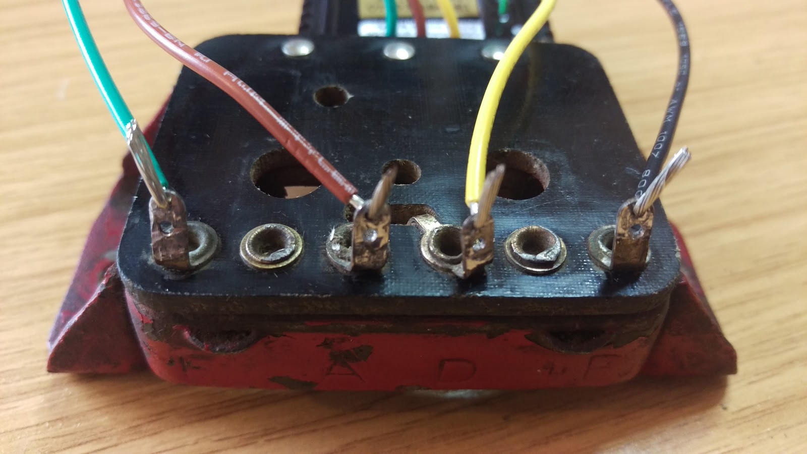
So here we have bared the wires and carefully threaded them through the holes in the correct terminals. BE CAREFUL! you don't want to get this wrong and destroy your new regulator. Bend the bare ends to align with the terminal and increase the strength of the joint.

Now solder the wires in place. Make sure you have heated the terminal effectively, so the solder flows cleanly and wicks into the conductor strands. Don't melt the solder directly with the iron, but let the work heat the solder - that way, you know the wire or terminal is hot enough to make a good joint. I'm using electricians cored solder here:
Coil the wires above the regulator such that they stay within the MCR1 cover, and retain with a small tie-wrap. We don't want to introduce a fatigue failure or have these wires trapped somewhere.
All done:
Finished, with no visible changes:
And the bike is charging: