Showing posts with label bearing. Show all posts

Wednesday, 17 June 2026

Magneto bearing puller

 With these old bikes every new job is a challenge. I suppose I could have sent the dynamo away to be refurbished like I do the magnetos but they're not that complicated so I do them myself. 

The E3 fitted to the Model A is a little bit different to the later E3Ls and E3HMs that I've worked on in that it uses magneto style bearings with separate races, cages and balls. Simple enough you might think - well yes, if it all goes to plan. 

What I discovered was that the reproduction armature that I bought for the E3 on the Model A, the first three-brush dynamo I have worked on, wasn't quite the same dimensionally as the old bent armature that came out and I found when I fitted the bearings for the first time that I had far more endfloat than I could cope with. To fix that you need to remove the bearing again, put a spacer in behind it to take up the end float, and fit the bearing back again - and you might end up doing this two or three times.

You need a special puller to remove the bearings and I found the details for one here:

https://www.kynoch-douglas-parts.com/html/articles/magneto%20bearing%20extractor.htm


The main tube part of the puller is made from a bit of old handlebar which I've turned internally to make the hemispherical form that will fit into the bearing race.


I turned up a plug to go in the end of that with an M8 female thread in the middle and welded it into the end of the tube. The six slots were cut with a hacksaw - you could make a much better job with a slitting saw but frankly I didn't want to work of setting it up.


There are a couple more details - the end of the threaded rod has a small disc welded to it to bear on the end of the armature shaft to reduce the likelihood of damage and the other end has a t-piece to allow you to turn it easily.


Here it is in action. Initially I used a regular worm drive jubilee clip to hold the six legs into the bearing, but they are just not strong enough and will pop out. The worm drive does not allow you to put sufficient force into the legs so I have used a much better quality hose clip - this trunnion type clip:


It works very well but you do need quite a lot of force to remove those bearings.


Friday, 18 November 2022

Pillar Drill Spindle Bearings

My cheapo pillar drill is a project in itself also I've had it for quite a few years now and it's had a few modifications to improve its performance .

I probably should have bought a better one in the first place!

This blog post was useful guide to what to expect when pulling the drill apart:

It's got a bit of run-out on the spindle and in this picture the run-out doesn't look like much. However the main problem is the quill itself which wobbles around in its bearings.


The pulleys are a bit loose too, but this is down to burrs and a loose grub screw


This is the return spring - simple, but appears to work adequately:


The three handles on the quill pinion constantly come loose and are now held in with Loctite:


I made this bracket to support the end of the depth stop and as a place to hold the chuck key. The bracket replaces a crappy plastic one that came with the drill and broke quite quickly:


Here's the top spindle bearing in the quill. There's no play here.


The play is here, in the body of the drill. There's not a great deal I can do to improve this...


What I've done is to put a screw into the body which pushes on the quill, taking out some of the play.


Another area of weakness is in the table which bends as it is only made of rather flexible sheet metal.


It can be stiffened up quite easily with the welder:


The next thing we might do is stiffen up the base of the drill as well, as again this is quite flexible. However this is only affecting accuracy if your work is standing on the base.

Friday, 18 September 2020

W/NG - Assembling the bottom end

I said the next step was to sort out the camshaft, and it was. The reason for that was that I wanted to replace the camshaft bush in the timing side crankcase before the crankcase halves went together and I have done that, because I have found the camshaft and I know what diameter the journal is - I'm confident that the bush can go in as-is, and not need reaming.

So without further ado I can clean the bearing journals and use the Rothenburger MAPP torch to warm up the cases and drop the bearings in, with their spacer and circlip on the drive side.


The crankshaft has been away at Alpha Bearings in Dudley, the UK's premier supplier of big ends for classic motorcycles who have replaced the big end and realigned the crankshaft at what would have been a very good price (and with a one-week turnaround) had the small end eye not turned out to be oval. I was aware that it was very worn and for some reason had no oil hole. The crank came back from Alpha true to less than 0.001" and looking excellent:


The small end eye now has it's lubrication slot. I had a small worry when I thought the mainshaft was not correctly pressed in - though Alpha's had not touched the shafts:


I spoke to Alpha and several people in the club about this suspecting that I knew the answer - it is a taper fit. Alpha explained that if this gap were absent, you could not be sure the taper was pulled up correctly - so that's another one for the memory bank. The AOMCC audience all concurred, so I am happy again.

So next, we are into shimming the crankshaft for the prescribed 0.008-0.012" endfloat. This is the set up I used - the DTI is actually attached to a magnetic stand on the vice anvil, and the heavy crankcase assembly is just sitting on the bench. Not ideal, but I found that if I move the crankshaft against the case using a twisting motion with a screwdriver (flywheel to inner case wall), that cases will not move at all.

In this way, I found that I had a total of 1.4 mm endfloat with no shims. That's about 0.055".


That's a start, but we need the correct endfloat with the rod in the centre of the crankcases. To do that, I used a bore gauge to establish a position where the rod to crankcase measurement was equal on both sides and measured the end float from this position.


I have some 0.3 mm (0.012") and some 0.5 mm (0.020") shims, of 26 mm ID. Time for some calculations:


That leaves me with 0.22 mm end float, or 0.0086". Perfect.


I bolted up the crankcase halves sealing the joint with Threebond 1215 and assembled the cases into the frame, fixing the front engine plates loosely onto the crankcases and then dropping the lot into the frame, retaining it with the single 1/2" stud at the bottom of the down tube. 

When you start on the rear engine plates, you do the drive side first, with two studs into the engine and hold the plate to the frame on the gearbox top stud, then pass the footrest bar in. If you don't do it this way you will never get the spacer in.


When that is done you can put the rest of the bolts and studs in with the timing side plate and the magneto platform. If you look closely you will see the bash plate fitted, though you cannot finally bolt this in place if you have not put the sump plate on.


You can see why the magneto platform needs those extra studs and bolts to stop it flapping about.


I made an earth wire for the magneto:


With it all tightened up, I did some trials with the timing case. Turning the engine over with the camshaft, rockers and half time pinion in place sounded awful, so I had to investigate.


That pinion is knackered. I also realised that the camshaft bush that measured up OK was actually oval - I should have looked for that before. It was OK in one direction but when I looked at 90° to the original measurement I could see it was quite worn.

The next step is to pull the engine out again, replace the camshaft bush and reassemble with a new half time pinion.

Sunday, 13 September 2020

W/NG - Preparing the bottom end

We're having a couple of days off from DIY, the railway and allotmenting and I've walked the boy so it's time for a bit of motorcycle activity. After putting another coat of black enamel on the Model A front mudguard and rear stand, I clean the bench down and pull the W/NGs cases out of the frame, where they were after the engine plate trial fit.

First job is to pull out the base studs and clean the gasket faces:


One of them is extremely stubborn and I elect to scrape around it. It's a bit more fiddly but we don't want to damage the stud or the case for the sake of making the gasket preparation a bit easier.

I've measured up the camshaft and the cam bushes in and found that the crankcase end camshaft journal is in poor shape - the wear is mostly in the camshaft. I'll seek advice on that one, but the crankcase end bush can come out when I pull out the old main bearings.

I use the excellent Rothenburger MAPP torch for this, with my infra red thermometer:


I heat the area around the bearings to 135°C, and this is enough to tap both bearings out in one operation:


The drive side has two bearings. One drops out quite easily at a similar temperature, along with it's spacer; the other is retained by a circlip:


This is a bit tricky, as son Thomas has my small circlip pliers but it comes out with the assistance of a scriber and a small screwdriver:


Next, we need to sort out the camshaft.

Tuesday, 21 April 2020

QR50 - Bearings & crankshaft

Bearings and seals - do they frighten and you and have you running for the Honda parts specialist? Are you scared off, because these things look like important bits of the engine and their failure will have you taking it all apart again? This is true of course, but usually these are just standard proprietary items that the original manufacturer of your engine bought from a specialist supplier.

You can do the same, in many cases.

You need to have a look at the shafts and journals that you want the bearing or seal to go in. In the case of the QR50, I had some old bits knocking about in the big bucket of parts which I could measure. It's useful to cross-reference the old bearing and seal dimensions with the dimensions of the crankcase openings and the shaft journals to check your selected sizes:


I use Simply Bearings for bearing and seal supplies, because they are reliable, offer a wide range of parts to suit your budget and they deliver quickly. They are at https://simplybearings.co.uk and if you select 'Deep Groove Ball Bearings' you will see this handy product finder which allows you to select bearings by ID, width, OD, fit, seal type, and manufacturer:


While you wait for your parts, make sure the cases are scrupulously clean:


Before you start, assemble the parts you received and look for some suitable drifts to put them in with. You will obviously only push the bearings on the outer race, wont you! Ball type rolling bearings are NOT designed to take substantial axial loads.


Check that they sent you the right ones...


Sit the bearing in the case. You will probably see that it doesn't slide straight in - it shouldn't. If it does, you will need some Loctite Bearing Fit (641, for example) to retain a loose bearing in a casing.


Usually though, if it hasn't been bodged, you will need to heat the casing up such that it expands sufficiently to allow the bearing to drop, or be lightly driven into place. Whilst I've used the oven to heat cases in the past, recently I have been using my heat gun without incurring any problems. This is a 1600 W gun, sold for stripping paint, and I heat the case until 'spit bounces off' as they say.


You can put the bearing in the freezer over night if you have to, and can get it into the 'heating workspace' without warming it up - and it will give you a bit of extra clearance. The thermal expansion coefficient of the aluminium casing is something like twice that of the steel bearing, meaning that you win twice as much clearance in heating the aluminium as you do in freezing the steel; then think that you will raise the aluminium temperature by something like 80°C (from 20°C ambient to 100°C). Reducing the bearing temperature in a domestic freezer could take it from your 20°C ambient to -18°C in the freezer, which might be -5°C by the time you transport it to the bench, so you gain something by doing that.

After that process, the bearing just drops into place:


You'll notice that it is proud of the inner surface of the crankcase. You'll realise that this bearing dictates the endfloat in the crankshaft, so you must be sure that the width of the selected bearing must allow the endfloat to be realised as the designer intended. This should be easy if you have the old bearing (and know that the engine was working with that bearing) but may require some measurement and calculation.

You'll note that the main bearings shown have no seals - you can see the balls. This is as the designer required, since this is a two-stroke engine lubricated by oil mist. This next bearing is the main output shaft from the transmission, the stub axle which carries the back wheel. It's fitted with rubber seals on both sides, since this bearing seals the transmission fluids from the brake drum. There is a third seal between this bearing and the transmission, with a drain hole between the seal and the bearing which you can see in the picture below:


With the main bearings in place, we can trial fit the crankshaft:


Here's the engine assembled. Unfortunately I don't have the casing screws at the moment so cannot finally close the engine up:


Monday, 14 November 2016

E3HM Dynamo

Well, the charging system is not working. Hardly surprising after an indeterminate period of laziness under the Italian sunshine, but the problem must be in the regulator, wiring or dynamo. The wiring is very simple and it's brand new; the dynamo needs inspecting anyway and is first up.

Removing the Dynamo

The dynamo is removed by releasing the clamp holding it onto the magneto and removing a nut drawing the drive end of the dynamo into the magneto drive cover. Suspicion is immediately raised by this screw:

Conspicuously shiny and really shouldn't be there!
There should be a little sleeve nut on a stud there. There is nothing too much wrong though - it motors when connected to a battery


View of the drive from the magneto. It was at this point I realised the whole magneto rocked slightly on the engine plates - not loosely, as though the mounting nuts were not tight, but as though something was bending.


The reason is that the fourth mounting is broken - we will have to invent a way of getting to that.

Broken 5/16" hex screw

Dismantling the Dynamo

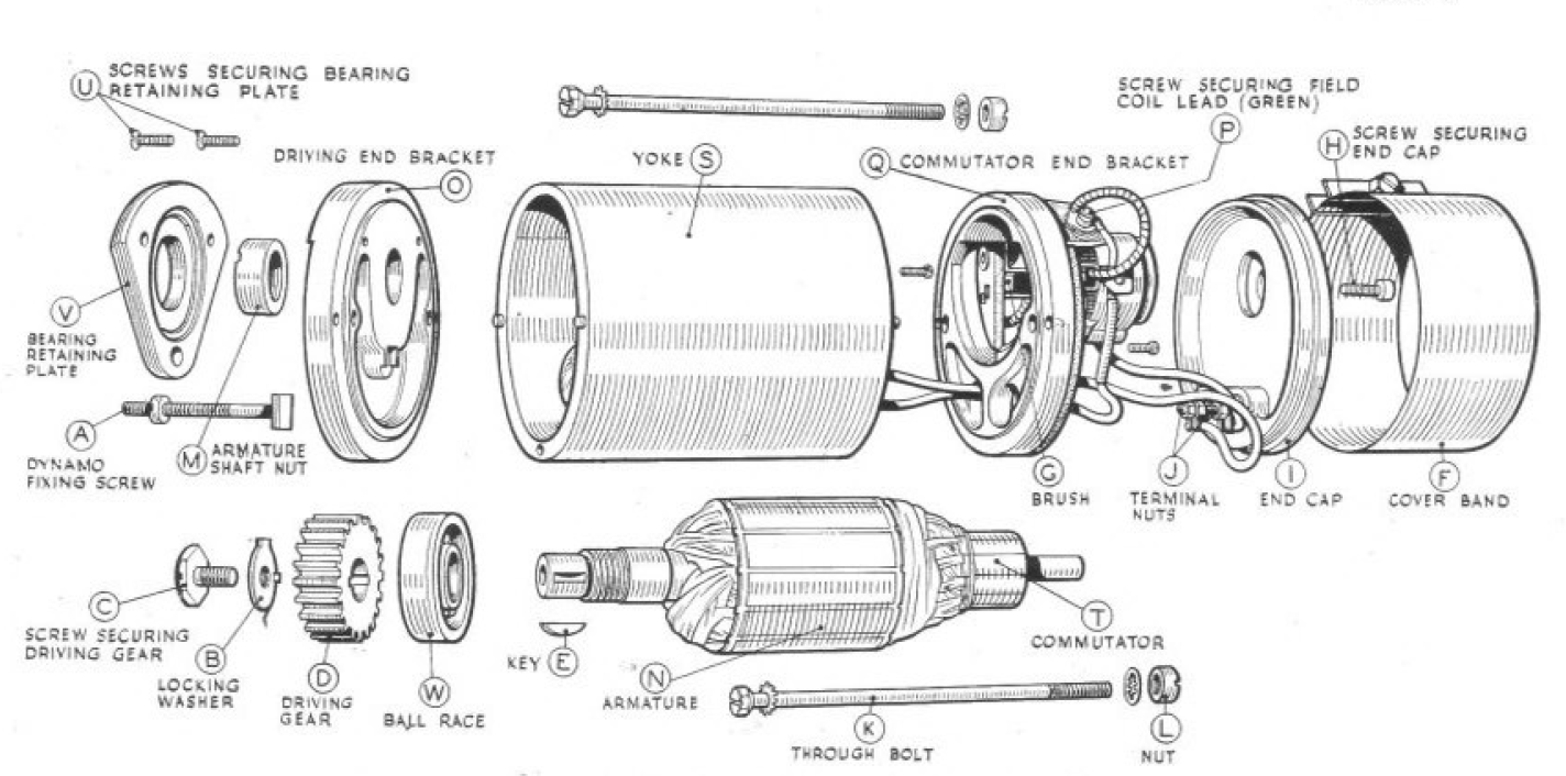
This handy diagram comes from the W/NG workshop manual.


The manual is also useful to show us how to take the dynamo to pieces.

Starting to look over the dynamo on the bench, we can see the drive end bearing retaining plate (Item V in diagram H13) is loose.

Stud and sleeve nut missing
Removing the commutator cover band by releasing the clamp screw on the cover band (F), we find the cork gasket looks like a tired bit of cardboard. New gasket required.


Greasy brushes:


Mucky scored commutator:


The next thing we do is remove the brass screw (H) securing the end cap (I). Next, we can remove the nuts (J) securing the D and F wires to the end cap terminals

Brass screw H back in place for safe keeping
Next, disconnect the wiring in the commutator end of the dynamo to allow you to continue dismantling.

Disconnect the earth side with this screw

Disconnect the D brush with this screw
Remove the wire link between the D brush and the D terminal on the end cap.

Wire link, D brush to end cap D terminal
Remove the brushes by pulling back their springs with a wire hook, small screwdriver or a small pair of pliers. Pull the brush out gently.

One of the brushes
With the brushes out, you can see the commutator.

Dirty commutator
The next job is to remove the armature. Grip the drive gear in the soft jaws and remove this screw, starting by knocking back the tab washer (if it is still there).


Sometimes the drive gear is a tight fit on the armature. Remove it with a small puller - watch out for the key:


Drive gear dismantled
Next you can remove the two long screws (K) running through the yoke (S). Grip the nuts (L) at the commutator end as you undo the screws.


With the screws out, the armature will pull out of the yoke. I didn't expect to see this ball bearing on the commutator end.


The next step is to free the drive end bracket (O) and the drive end bearing retaining plate (V) from the armature. We'll need to remove the armature shaft nut (M) for this. This has two slots in the top and needs a special tool which I cut from a damaged box spanner:


After some filing and a dose of case hardening it is ready for use:


With the armature in the vice in soft jaws, the tools, equipped with a tommy bar makes short work of the slotted nut.

Rebuilding the Dynamo


Drive End Bearing


Someone has mangled the drive gear journal with a punch - that will clean up easily. The bearing is held in place with these screws. Unfortunately, that fine thread is a poor choice in this soft alloy and one of them has stripped. It's only 73 years old as well...


The bearing is very rough. We'll measure it up and get a new one.


Like this:


It's a double sealed bearing, so that it will retain its own grease and prevent oil coming into the dynamo.

The bearing retaining plate (V) is, as I said, loose. We'll need to repair those tiny stripped screws - I have decided to replace them with 4 BA screws which are slightly larger and will be stronger, especially as I will run the tapping size drill right through the driving end bracket (O), so the screws will be longer. Countersunk 4 BA screws will still fit in the original holes in the plate.

Recutting the drive end bearing threads
The result is quite neat:

New 4BA csk screws in brass
With the drive end bearing assembly complete, we can refit the armature with its nut.

Armature reassembled into the drive end bearing
Next we need to look at the other end.

Commutator End Bearing

The commutator end is still a problem. This is the journal for the bush - the bush ID is 0.318"; this journal is 0.275" OD, which is very undersize...


The rolling bearing should not be there on an E3HM; it maybe home made - there is a journal machined in the end bracket and as previously noted, the journal for the oilite bush is undersize. The bearing is 22 mm OD;


Unfortunately, the journal diameter in the commutator end bracket (Q) is larger.


It's actually 22.5 mm ID. I'm wondering if this was meant for a 7/8" bearing, which is around 22.25 mm OD. They are cheap, and I could order a double sealed (2RS) bearing which would last a while but these bearings will be too large on the ID. Whoever modified this, and it is non-standard, ground the armature to suit the 22 mm bearing. I have no choice but to shim the journal to suit the bearing, which works fine.


I can refit the through bolts and nuts (K) and (L) and move on to the commutator. These are fitted with shakeproof washers both ends - I must remember to fit them when I find some!

Commutator

Once the bearings are sorted, the next step will be to rebuild the commutator. The first job is to thread the field coil leads through the fibre plate on the commutator end bracket (Q)  and fit the plate with the three tiny screws:


I have a set of NOS Lucas 200290 brushes, all the way from Australia:


Holding the springs back, slide a brush into each holder, checking that it is free to slide. Mine are a bit tight and will need a polish. Let the free end of the spring rest on top of the brush:


Wiring Up

The link connecting the D brush to the terminal on the end cap was horrible, as shown earlier. We need a short piece of wire and a couple of small ring terminals to fix it:

Crimped and soldered
Connecting the wires back up is simple, but it pays to be careful with the routing. Try the wiring with the end cover loose:


Its quite tight in there, and the D wire passes closed to the F terminal:


Testing

Quite the easiest way to test the dynamo, re-magnetising it in the process, is by causing it to 'motor' - that is, driving it from a battery and causing it to behave as a DC motor.

To do this, connect the D and F terminals together (I use a small crocodile clip to span the terminals - one jaw in each hole). Connect the case of the dynamo to your battery's earth terminal (negative in the case of the W/NG) and the other terminal (positive in my case) to the crocodile clip. The field coil and the armature are thus both exposed to 6V, and the dynamo should smoothly turn, relatively slowly, in the direction that it will run on your bike. In the W/NG's case this is anti-clockwise when viewed from the commutator.

End Cover

The commutator end will need a new cork gasket. The originals were riveted in place with the bifurcated rivets still remaining in this band:


I've cut some holes with a wad punch to allow the band to fit in place without removing the original rivets:


Drive Pinion

Refit the key and slide the pinion into place. The pinion is retained with a 1/4" BSF screw with an oversize shallow hex head; this is retained with a tab washer. Pimple the tab washer into one of the pinion keyways, and when the screw is tight fold up the tab washer against a flat on the hex head.

A 'before' picture of the drive pinion

Refitting the Dynamo

Once the end cover is back on and the sleeve has been tightened down, you can refit the dynamo. Grease the magneto drive pinion by turning the engine on the decompressor, then slide the dynamo into the retaining strap. Draw the dynamo into place using the sleeve nut.

The sleeve nut whose absence started it all
You can then tighten the strap screws with the special dynamo spanner and refit the yellow and green dynamo and field wires.

Dynamo spanner

Dynamo & field wires