Showing posts with label plunger. Show all posts

Thursday, 1 September 2016

Charlie's Shed - Curly copper fuel pipe

We'll need a new copper fuel pipe for the W/NG, like this fine example from Paul Slootheer:


It will need curls to give it some flexibility and it will need to be annealed after bending. We don't want a fracture out on the road, pouring fuel over the dynamo.


We'll use these soldered unions & nuts.


Here is another reference point:

Barn find NH, stored since 1960
Using Paul's guidance & some hints from Nev Hunter I've made a pattern from a thick piece of plumbers solder. You can see the fuel tap here as well, which is a re-sealed original but has a repro hexagon shaped reserve plunger:

Three tight curls
Two looser curls, more suited to 1/4" tube
Using some 1/4" copper pipe, we'll bend up the real thing. It's important to think this through, bend by bend and perhaps to buy enough pipe to have a second crack at it if it all goes horribly wrong!

Take it slowly; you have to realise that in bending the pipe you are aiming to stretch the copper on the outside of the bend. You can avoid flattening the pipe by filling the pipe with sand or solder, but if you are gentle and controlled this is not really necessary and was certainly not done by the factory. Use a hardwood former - I used a 1 3/4" oak dowel, that I used as part of a kitchen worktop project.

The first bend
The first bend is an easy right angle bend around the former. Make sure there is enough length to bend up the tail into the bottom of the float bowl later on.

First bend against the pattern
Start to form the curls by clamping the downward tail against the former in the vice This is probably the most difficult part of the whole operation.

Holding the first bend in the vice and starting the first curl around the former
The design of the vice usefully allows you to trap the downward tail in several positions as you form the first curl around the former.
Moving the downward tail around the vice and continuing bending the first curl

Moving the downward tail again, and complete bending the first curl

Moving the downward tail around the vice again and starting the first second around the former

The curls, finished
Once the curls are finished, have a good look at them against the pattern. This is where the pattern is most useful, as until you cut the copper pipe to length you cannot really fit it against the bike.

Add the upward bend toward the tap

You can now put in the last bend, which is the U bend beneath the float chamber. This is simply bent around the former, making sure that start of the bend is in the approriate position to allow the finish to land in the union beneath the float bowl.

Roughly trimmed to length
I'm currently waiting for the tank mounting rubbers to turn up. Until they do, I'm not sure of the final resting place of those ends...

So, with the tank bolted in the correct position we can try the new fuel line in place and trim it to fit. Attach the nipples with their nuts (but without the fuel line) to the petrol tap and carburetter and offer the fuel line up - I put the end of the line in the carburetter float bowl union first since this is least accessible. The most important thing here was to get the fuel line to avoid the dynamo and the advance retard cable:


This meant that I had to cut the carburetter end of the line as close as possible to the bottom bend, to get it as high as possible. This done, I could set the line in the carburetter end and see where the other end was going to fall. With a little trial and error, remembering not to cut too much off at once, I got pretty close:


I need about another 1/4" off the tap end. Cut with a tube cutter or a hacksaw, deburr properly and blow out the line:


Since you are cutting tiny lengths off at this stage, its easier to use a hacksaw. A tube cutter crushes the tube a little which is a problem when cutting short lengths. Another 1/4" should do it:


With the nuts in place, it is stiff enough to do some final tweaks on the bends, in my case to avoid the dynamo:


Ready for annealing & soldering up. Not looking too shabby:


Next step, before soldering the nipples on, is to anneal the pipe - in other words to remove the work hardening stresses that have built up during bending - I am sure you noticed it got stiffer after bending? You don't want to leave the pipe in that state, because it is going to bend a little in service, through vibration, and this will make it harder still eventually leading to a fatigue failure.

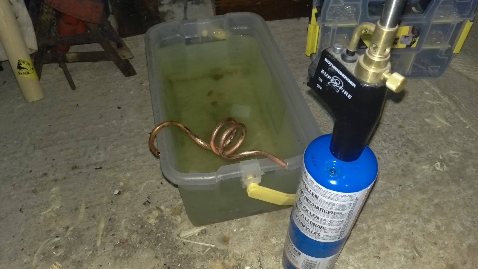
For copper, the annealing process involves heating the material to cherry red and quenching in water. No problem for the mighty Rothenburger torch, even with propane in the tank. You will want to clean the scale off with wire wool after annealing.

Be careful with the pipe from now on - it is very soft and will bend very easily.


Tin the ends with solder after fluxing; put the nuts on the right way round, and sweat the nipples on. I use a small butane torch for this - do not overheat the joint, or the solder will not take.


Finished.


Friday, 27 February 2015

Dealing with teething trouble...

So this week, I've been out and about for another short ride, but first I refitted the Morgo pump. I did about 8 miles as usual, out of town and up to 40 mph. The lubrication job I did on the speedo seems to have stopped it sticking at full range.

The Morgo obviously provides more oil flow than the plunger pump, and I finished the journey with about 10 psi on the oil pressure gauge.

I also finished the journey with a completely flat rear tyre, which looks like it might be a valve failure. I wobbled along the road, complaining about the tramlines the council left when they resurfaced, only to keep my wobble, rapidly turning into a squirm from the rear end, when I ran out of tramlines. I recovered the puncture with a handy can of tyre weld I had in the pannier.

Of course, the low oil pressure problem is not sufficiently improved with the Morgo to use the bike in anger. Lifting the rocker covers with the engine running (rather dangerous - they are very hot) you can see little jets of oil coming from the rocker oil holes. I've fitted three new old stock rocker shafts to deal with the wear I found in the shafts last year - one was already fitted due to a damaged thread:


A thought occurred to me, corroborated by AOMCC forum members - retarded ignition causes overheating. Checking accurately revealed that the ignition was indeed retarded: I moved the distributor about 10 degrees, equating to about 20 degrees at the crankshaft, to get it right (thanks MikeN!).

So we will have to see what happens. Just waiting for a new inner tube...

Friday, 5 October 2012

Can't stand the pressure...


Now, I have acquired a few bore gauges and this evening I have broken out the trusty old Moore & Wright micrometer and I have measured my oil pump. Here are the dimensions:
  • Return bore diameter = 0.499" - 0.500"
  • Return plunger diameter = 0.499"-0.4995"
  • Feed bore diameter = 0.437"-0.438"
  • Feed plunger diameter = 0.436"-0.4365"
Now, seeing as Mr Waller specified 0-1 thou clearance for the singles, I reckon my pump is in pretty good shape. I have max 2 thou clearance on the feed side and max 1 thou on the return.

The drive block is a different story. I have a block that varies 0.561-0.5635"; the 'groove' the block runs in on the feed plunger is 0.573 - up to 12 thou clearance. The return side is better, about 0.570, or max 9 thou clearance.

What do you all think of that? Good to go back in the engine?

I also took the opportunity to flatten the mating face - you will recall there were some little wobbles on the thin bottom edge. All gone now:

Friday, 28 September 2012

Is it time to strip the engine yet?

Well, what delights will we find under here? 

Since I have not been able to shift the head, despite undoing all the fasteners (no I didn't miss any) I have decided to attempt to remove the barrel & head together and biff the head off the barrel using a block of wood from underneath.

Thanks to the ever-helpful Brenton Roy for that most excellent suggestion!!

The only challenge is that now I must undo all the cylinder base flange fasteners, several of which are inaccessible due to the dynamo and the timing cover. So, off with the timing cover! Unfortunately my imperial  hex keys were not at home - so I had to wait a little while. It's interesting that someone has fitted a set of cap head screws to this engine, so it's likely that someone has been in here before - which I guess is almost inevitable on a 60 year old machine. 

However, it comes off very easily, apparently with no stripped threads, though there is a quite a lot of Red Hermetite about.

Here's what I found:

Nothing too appalling at first glance. Everything in it's proper place, nothing mangled, the chain looks good and the tensioner is all there.

It's quite dark though. Is this evidence of a lot of blow-by I wonder?

Looking a bit closer, there is quite a bit of wear where the chain tensioner bears on the case - but this is probably normal and inevitable since the blade is free to flex at this end and the chain tension forces the blade against the soft aluminium case.

I'm not too worried about that.

But see what is missing? I didn't remove the nut on the end of the dynamo drive shaft! It's gone! Thankfully, unless it is stuck to the inside of the timing cover (I haven't looked yet) it must have been lost last time the engine was apart. There doesn't appear to be any damage from it flying about inside.

What else?

This is a bit peculiar - the tab washers for the oil pump haven't been bent up.

The alloy block and the two plungers are free - we will have to see what tolerances are specified for these parts.

Next stop we need to figure out how to time the engine so we can put it back together. Then it is dynamo off, oil pump off & we will attempt to remove the barrel  What fun! I might do some polishing first through, so I can clear the bench of the rocker covers and timing case.


Monday, 27 February 2012

Frank's Linked!

So, time to start assembling. This shows the rebound springs, the sliders, their posts & pins in position on both sides with the chrome shrouds slid into the frame. Above these are the main springs with their caps, ready to be pulled in.

Missing from this first picture are the stand brackets which have to fit on the end of the springs, the horseshoes and the links.

In the background, you can see the rear wheel waiting in the wings!
The next step is to pull the springs into place and fit the nuts and the stand brackets to the bottoms of their pins. This is not too difficult, since you can trap the slider against the bottom of the frame with a G-Cramp or a cargo strap, and compress the rebound spring; then you can get another strap or clamp on the top of the pin, against the bottom of the frame again, and pull the main spring down until the end of the pin emerges through the hole in the bottom of the frame lug.

When you've done all that, you can slide the stand bracket into place over it's lug and put the bottom nut on - the only difficulty I had here was to get the pin central enough to get the nut on.
Pushing the slider around allows that to happen OK.

The next step is to add the horseshoe, it's pin, knurled washers and nut. That done, you can put the links on and wiggle the pivots into place.

All I need now are some stainless washers & nuts for the links; and some suitable stainless fasteners for the stand brackets.
I've put an order in to Draganfly for the rear stand, the springs and the mudguard stay mounting studs. While we wait for the parts to arrive, we will have a look at the forks.

Monday, 6 February 2012

Amelia's Plungers

So, we spent the weekend cleaning, painting & collecting pieces of suspension from the boxes the machine was delivered in. We are missing a washer (!) which will have to be made and we were missing the two large upper shrouds (the ones with the slots in) which came from eBay, with better lower shrouds than the ones I had.

Generally the bushes are good - the tubes along which the sliding members move are a bit pitted in places. Some threads need recutting as well.

The chrome plating done by the previous restorer is flaking and will have to be removed - the link pins are especially bad. However since the first build is to be non-cosmetic, we will leave these for now.

Draganfly have the rear stands in stock, so when I have acquired the material to replace that washer we will take a trip down there and pick one up, along with the springs, the mudguard stay fixings and various other small parts. We'll go to Mike Peters at www.polished-stainless.com for all the stainless fasteners (as we did for the Bantam).

However for now, the plungers are loosely fitted in the frame:

And this is what it will look like:


Frank's Links

So, to bike building, starting at the back.

My Square Four, like many others is fitted with the famous Anstey Link rear suspension, designed by Frank Anstey to overcome the chain-tension problems inherent in the plunger design, whilst avoiding the complex frame re-engineering required when providing a true swinging fork. Mr. Anstey joined Ariel from Triumph, as Ariel's Chief Designer, in 1937. Here's an extract from Patent 498544, filed by Ariel Motors & Mr. F Anstey on 16th December 1937:

Patent Number 498,554. Spring frames for motorcycles. ARIEL MOTORS, Ltd., and ANSTEY, F. Dec. 16, 1937, No. 34840. [Class 136 (iii)] A spring mounting for the rear wheel of a motor-cycle comprises in combination, ...on each side of the wheel, a lever j arranged horizontally or nearly so at the rear end of the frame a, one end of the lever receiving one end of the wheel spindle m, as by means of a slot k, a fulcrum piece g having a pivotal connection, i with an intermediate part of the lever j means for carrying the fulcrum piece g on the frame so as to allow it to move in a vertical or approximately vertical direction, and means for attaching the other end of the lever j to the frame so as to allow this end to move in an approximately horizontal direction, as by means of a vertical link n or a horizontal guide, the movements of the parts being controlled by one or more springs.; The fulcrum piece g is slidably mounted on a guide pin f secured in a bracket c formed on or attached to the rear end of the frame a, the sliding movement being controlled by a main spring h and a rebound spring or rubber buffer, with or without a vibration damper, such as an hydraulic damper combined with the guide pin mounting. The lever j is formed with a forked part passing around the bracket c, the pivot pin i extending across the forked part. Thesprings are enclosed in telescopic tubes t, u. The two levers j on opposite sides of the wheel may be interconnected by links &c. and controlled by a single spring or set of springs

The  design uses all the 'normal' elements of a plunger suspension, but instead of suspending the wheel from sliding member it incorporates a cast steel horseshoe, which carries the wheel and pivots on the sliding member. This horseshoe is retained by a link, pivoting above the lower frame members and forward of the plunger allowing the horseshoe to travel through a short arc so that the drive chain tension was kept more constant during compression and rebound. Of course, this is not a perfect solution since the centre of the horseshoe's rotation is still a long way from the gearbox sprocket centre, but it is a lot better than a conventional plunger.

Of course, there are lots of pivots, sliding members & bushes to wear out...

Here are the bits I have acquired:


You can identify most of these from the sketch above. The long screw poking out of the horseshoe (and painted that WD green colour) is the chain adjuster, which replaced the snail cams. You will also see that my '51 bike has volute-type rebound springs in place of the previous coils.