Showing posts with label fabricate. Show all posts

Monday, 10 January 2022

FH Dry Build - tail light plinth

 The FH, along with other swinging arm Ariels of the period has an unusual feature used to mount the tail light vertically - a little pressed steel plinth, part number 5611-55. Drags do a very nice replica for about £15, but they have been out of stock for a while and it is an easy thing to make.

Starting with the Lucas 564 rear lamp, we need a caliper, some plastic holes, a piece of card and a scalpel.


I used the holes and the caliper to mark out three holes in the card - one for the bulb holder and two for the mounting bolts. Then I can fit the lamp to the card and draw around it:


Next, I can develop the part around the shape of the lamp: 


Cut it out with the scalpel, using a wad punch for the holes if you have one of a suitable size. In my case, I punched the smaller holes and used a swivelling scalpel for the larger one:


Next, make some nice sharp folds with a ruler and use staples or a glue gun to fix the edges which will eventually be welded:


Now, we can do a test fit and trim the pattern to allow the lamp to sit vertically above the number plate:

With the part to the shape we want, we can undo the staples and stick the pattern to a suitable steel sheet. It's that old bread bin again, that gave us the air filter for the QR50:


I used the bandsaw to cut it out, but you can use a hacksaw, shears or whatever you have. The edges are cleaned and deburred with a variety of files.


Folding is quite straightforward using just the vice and my trusty bit of copper bar. With folding completed, the next step is to weld up the joints - most of which came together to weld autogenously. The linisher springs into action to clean it up:


After a couple of trial fits and a bit more time on the linisher, I treated the plinth to a bit of UPol etch primer before fitting it to the bike - temporarily, with a few magnets:


I think it looks fine.

Sunday, 4 April 2021

QR50 - Fabricating the Airbox

Building a replica airbox seems like overkill for a little motocross bike that's going to be worth a few hundred quid when done, doesn't it. The original plan was to use a cheapo Chinese pod filter on the carburetter intake, £6 max and you are done, and maybe put a toolbox in the airbox space. However, as usual my OCD took over and fuelled by the fact that the carburetter moves relative to the frame and a pod filter wouldn't fit in the space available without an elbow, and then it would need support... you see how the job grows. I elected to fabricate the airbox along the lines of the original - then I'd have support, the space filled, an air filter, no cash outlay and something that could accommodate the carburetter moving up and down. Plus, I'd have more experience to help when I came to manufacture the toolboxes for the 1930 Ariel Model A.

So, out with the cardboard to make a model, the beginning of a lot of my fabrication jobs. Cardboard is great - you can make an airbox, cut it where it doesn't fit, take it apart, make a better one and eventually you end up with one that fits, like this one:


Here it is in situ:


The next step is to cut it apart again and make the net - the pattern that will be used to make the part in steel. I like to use these magnets to hold the net on the piece of sheet - this is 0.9 mm thick cold rolled sheet, part of an old bread bin.


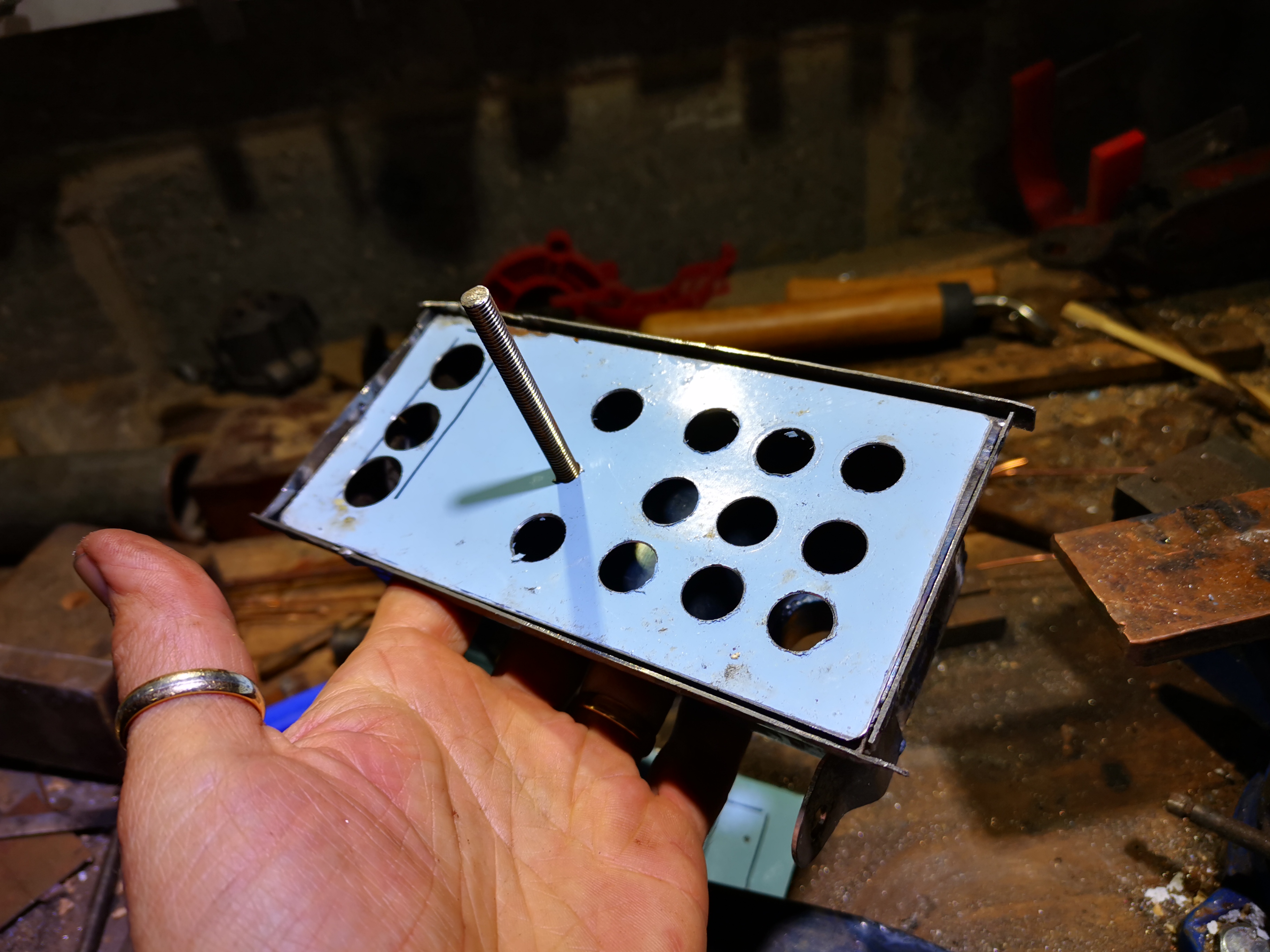
You can use the bandsaw to cut this stuff easily, though some of the internal features need a file. It's important to deburr and to file your corners square before you start folding:


First job, cut the hole for the air outlet. Normally, it's better to cut holes after bending when the hole is near a fold, because the bending the sheet will stretch the hole out of shape. In this case, I wanted to corner weld the tube in from inside, so the hole had to be cut and the weld completed before the sides were folded up. It's critical to plan the process to make the folds as easy as possible - it is all too easy to make one fold only to realise you have prevented yourself getting access to make the next one.

I always drill holes using cone drills - it's much easier to get a circular hole in sheet metal than using a twist drill.


The air goes into the carburetter through a 1" tube, welded into the box:


The most complex fold is this curve - it's there to go around the frame. I made it round a bit of scaffold pole and when it was almost there I folded up the sides to make sure it was the right shape


In case you were wondering, I burnt the blue powder coat off...


At this stage, I welded up the edges of the curve, before I made the next folds - to ensure the material would stay in place while I subjected it to more bending. This picture shows most of the bends complete and welded:


Here, I've folded up the flanged edges and tacked on the lower mounting bracket. The tube going to the carburetter has been trimmed to length:


This is the lid, made in a similar way:


Back to the airbox again, this blue panel supports the foam:


Here's the other side, showing the inlet to the airbox which shields the oil line banjo and ensures the air inlet is protected from flapping trousers:


View from the front. That nut is attached to a stud that passes right through the lid, filter element and box and is welded into the back of the box:


Next I spent half an hour tidying up some welds - I used the linisher, some files and a small wheel in the Dremel just to smooth it out before painting. It's not perfect - I'm not spending hundreds of hours ironing out every nick and scratch but we will tidy up the worst of it. So next it's paint, starting as usual with U-POL etch primer.


Here's the completed airbox, coated in U-POL satin matt black. The parts are held together with hot melt adhesive and the element is hand cut from a piece of open cell foam:


Here it is in situ, from the top. I had to change the top bracket since it wasn't sitting square in the frame


Saturday, 7 December 2013

Coil Mounting 2

Apologies for the time I've taken with this, but life (actually DIY) gets in the way sometimes.
 
This started life, as most of my fabricated parts do, as a piece of cardboard. It's cut from 16 swg cold rolled sheet, and will carry the coil vertically, mounted on the Lucas bracket in those two holes in the middle.
It mounts from the shouldered nut under the seat, and will fix to the gearbox top bolt.


Here it is again, after some redesign, with the bottom bracket tacked in place. I've tried to use 'styling' ideas from other Ariel components, to make it look as if it was designed in Birmingham in the 1940's:


And from behind. I will probably make those nuts captive, otherwise removing the coil will involve removing the bracket:


And various shots in situ. It now has a stiffened edge:


Looks tidy around the gearbox top bolt


Looks a little too close to the battery carrier. I will move that bottom bracket a little.


Painting next.


Saturday, 28 September 2013

Batteries

As I've mentioned before, I have a very nice GRP battery box from Draganfly, made to look like a Lucas GU11E battery. Here it is:


Now, the original GU11E apparently has a 20 Ah capacity, which is the peculiar way in which our industry has chosen to illustrate the energy capacity of a battery - it means it is capable of delivering a current of 20 Amps for an hour, or 40 Amps for half an hour, or 10 amps for 2 hours - you get the idea.

Now an Ampere, or Amp for short, is a unit of current, and current is the rate of flow of electrical charge - measured in coulombs. So an Amp is a way of describing coulombs per unit of time - 1 amp represents 1 coulomb per second of flowing charge. So, if you multiply Amps by time (As in Amp x hour = Ah) , you get back to charge again - and units of charge are what is stored in our batteries.

So, in order to get my bike to run for a reasonable period of time without being charged (for when I choose to ride at 10 mph in a traffic queue on the M25 (when did you last see a Square Four do that?)) I need a battery of sufficient capacity to deliver sufficient current for the time I am riding so slowly that the battery is not charging, without running flat and bring the bike to an undignified halt.

You see, according to this chart I draw from the data in the C35SD dynamo instructions combined with some details of the Square Four's performance (and assuming the C35SD runs at engine speed, which it does, more or less) the dynamo does not start charging until you are moving at about 20 mph. So, go slower than this and the battery is draining.


But how much current do I use? Let's work it out:
  • my headlamp will use up to 55W, which at 6V needs just under 10 Amps to deliver the power (Power, W = Potential Difference V x Current A)
  • my tail lamp will use 5W, which needs another Amp
  • Lets assume the ignition coil will need 20 W, or about 3 Amps
Which gives us around 15 Amps, allowing for infrequent use of the stop light and horn. A 20 Ah battery will be flat in 1.334 hours, or 1 hour and 20 minutes. Reasonable? Lets hope so.

So we know what we are aiming at - a 6 Volt battery with capacity of around 20 Ah that will fit in my neat little fibre glass box. Since a year or so into having the Bantam, Beattie has been using a sealed lead-acid battery - the electrolyte is treated to form a gel, so it can't flow out, and the chemistry is altered somehow (I'm not that clever) so that when the battery is charged and would normally produce free oxygen & hydrogen, the gases recombine as water, replacing the lost liquid in the cell. This is really neat for a motorcycle, because it means you can fit them wherever you want (they are really small), they don't drop nasty acid all over your bike (how many rusty battery carriers have you seen?) and because they are made for things like burglar alarms, they are really cheap.

The downside is you cannot abuse them as you can a traditional wet battery - if you overcharge them and lose the electrolyte, you can't replace it.

The thing is, I came to use one of these things the first time because I realised the rudimentary (putting it kindly) charge control system on the Bantam was boiling the original wet battery - so I added a modern solid state regulator/rectifier (from the marvellous Rex Caunt Racing) and was able to use a gel battery. The one on the Bantam is tiny - about 3.4 Ah I think, at 12 V, and has coped perfectly for several years. It even remains charged through the winter, something the old wet battery could never do.

Monday, 6 May 2013

Shrinking & pulling

After the gearbox was back in, I decided to have a bit of an interlude and sort out some of the fabrication jobs that had been knocking about.

Finding myself with a spare hour or two one day, I made a start on the dent in the oil tank. The tank has had a major league ding in it for some time. Some was on the AOMCC forum suggested it may have been a battery explosion - it looks more like someone has used it for target practice.

Taking inspiration from a good book 'Building Budget Brits' I decided to use a method involving brazing & pulling to remove the myriad of dents in the tank. Some of them were very deep & localised, clearly with a lot of stretching going on. Now I could have filled or lead loaded this tank and avoided all the work, but I'm keen to learn and try new things....

So the idea is, we pull the dent out without holing or cutting the tank by fixing a suitable stud, wire, piece of scrap to the bottom of the dent and pulling it outward. I'd hoped to be able to weld to the tank and to pull the dents out with the tank hot, much like I repaired the breather tower. However, I was a bit concerned that I might just end up holing the tank, weakening the area around the weld and pulling or tearing the material.

So I elected to braze plain steel nails into the bottoms of the dents and pull them out cold. This would be OK, because during multiple brazing operations the material would be annealed several times. Then, I put a steel bar across the panel being worked on, to act as a fulcrum for the pulling operation. I used a pair of combination pliers to grip the nail and pull the dent out.

So here is the first pass


Nails resited, here we go for the second time..

and a third attempt

and again - four times now...
So before the fourth attempt, we had created several 'peaks' to go with the considerable troughs already in the tank. Levelling the peaks gave us an opportunity to lose some of the stretched material, by locall heating (bright red) in the area of the peak and reducing the height with some light hammer blows.

This is almost at a stage where we could use some filler... Lead maybe...

But, reasoning that this was going well and I could get more of that dent out, I pushed on with a fifth go at shrinking & pulling. This was lower but more level until i cleaned the flux off and I realised the 50 year old steel had cried 'enough'! Take a close look at the picture and you'll see a lot of cracks have appeared:

I think that this is due to hardening. Of course, annealing or normalising steel has a time element to permit removal of stress and changes in the grain structure and of course cooling this thin material happens very quickly. Added to that, the material was obviously thin from 50 years of corrosion.

Max was very concerned:


Wednesday, 6 March 2013

Hack & Slash

Spurred on by idleness, I have done a drastic thing to my original mudguard at the rear - I have sliced it almost in twain with a hacksaw.

The issue is that to get the L-stays into their studs at the top of the spring housings, I had to put a lot of pressure on the mudguard.

The reason is that I have, whilst reinforcing the mudguard, inadvertently straightened it out too much.

First I made one saw cut in each side, than I flexed the guard so that the L stays fitted into their lugs.

I found that my saw cuts had closed up completely. I then made a second cut, which partially closed up. Now I had no tension in the guard and I had a gap in which to re-weld.

Now all I have to do is weld it up again.

Brake Light Switch

The devil is in the detail, they say. Casting around for small jobs, I realised that I had nowhere to mount the brake light switch. I knew from studying the wiring diagrams that Ariel began fitting brake lights to Square Fours around 1953, so that early Mk 2s would have factory fitted switches.

A plea on the AOMCC forum yielded this picture, from Greg Snyder in Pennsylvania, USA:


Greg also posted this, of the bracket in situ on his bike:


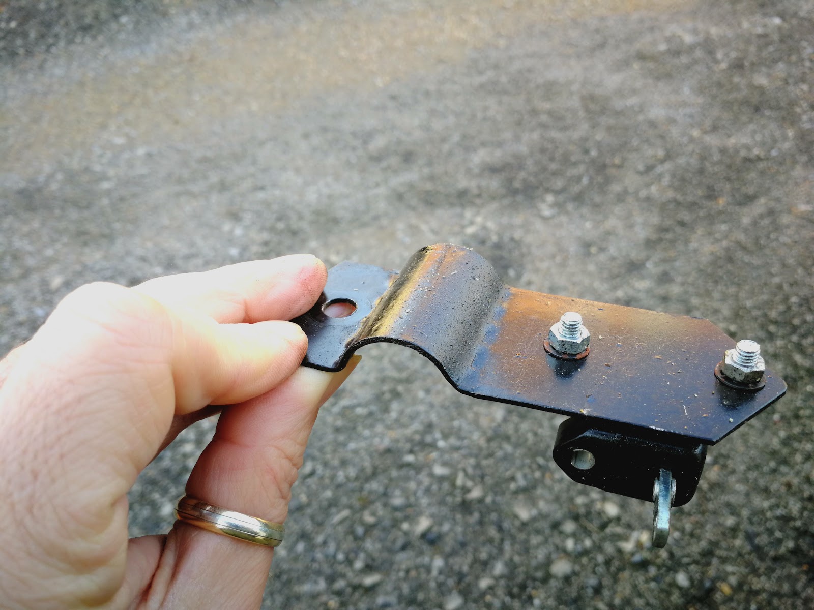
So, with guidance like that it was easy to make a new one:


Here are some details. Sorry about the sawdust:


And some more views: