Showing posts with label lathe. Show all posts

Monday, 19 August 2019

W/NG Handlebar Upgrade

Updated: First published July 2018

Living with the W/NG for a while now - coming up two years, I have realised that I don't like the dropped handlebars as they make you hunch down over the front end. Since the W/NG is great for pootling about the countryside looking at stuff, it needs higher bars - and since I like originality in my bikes I decided to look around for a pair of the original Ariel bars, which are tapered from a 1" central section to 7/8" at the ends.

I was lucky enough  to pick up a set of taper bars from Guy Hovey, of the AOMCC. They looked a bit odd - Guy said they were bent, which they were marginally, and I managed to fix that with a plywood jig and a dose of burning MAPP gas. What was more 'disorientating' at least to the eye was the fact that they had been shortened by an uneven amount at each end, which made them look more bent than they were. Careful measurement with the dividers found that eventually, and I have described how I fixed that in this blog post. It should make a good guide to show others how to repair or extend motorcycle handlebars. You'll note though that the repair is not in a stressed part of the handlebar - it is less than 2" at each end. If the repair had been in a location with a significant bending load, I would have added a solid steel internal spacer to bridge the joint, probably about 2" long.

There's a few pictures a bit further on.

Onward and upward, I found a set of Czech-made levers on eBay, at a good price - good because they were for 1" bars. Not to be deterred and making good use of the mini lathe, I knocked up some brass spacers.

They are made from 1 1/4" brass bar:

Brass bar in the lathe, supported on the revolving centre


Turning the spacers

Drilling to 13 mm

Cutting the 7/8" bore


Parted off from the bar
You will note in these shots that only one of the spacers has both flanges - one has a flange machined off to accommodate the 'web' that the clutch and brake levers mount to.

Marking out for cutting

Almost there

Small flat required to clear the levers

All done

Moving back to the bars, I needed to establish the original length and make the appropriate extensions. Nev Hunter, Australian AOMCC member told me that the end to end dimension was 71.5 cm on his original W/NG bars. Mine was 63...


So, seeking some bent MZ bars from the scrap pile, I cut a couple of sections and squared them up in the lathe. Having squared up the cut ends of my tapered bars with a file, I aligned the two pieces with a piece of copper tube:


I tacked them up in a couple of places with the TIG set before welding.

We call this an autogenous orbital butt weld, when we are welding hydraulic tube together. I held the TIG torch in place and moved the bar to produce a neat peripheral weld:


Gas was set to 5 l/min and the current to 45A.


I used a 1.8 mm electrode, #4 shield. The electrode was fully shrouded and ground to a sharp angle to maximise penetration:


All done
I marked out the length using dividers, measuring inches from a centre point:


These marks show inches from the centre to each end:


I learned that the total length of the tube was 31 inches. Using Nev's information,  I made a square cut at the 15 1/2" mark at each end.


When I'd finished I squared those cut ends up in the vice. Happy with the result, I mounted up all the handlebar equipment to have a look:


Half an hour with some 60 grit emery tape saw them ready for some etch primer:


This is what we are aiming at:


And here we have the finished article:


Today, a year or so after I wrote this post I have updated the handlebar layout to reflect the longer grips the W/NG would have worn:


Thursday, 22 November 2018

Gudgeon Pin Extractor

Gudgeon or wrist pins retain the piston to the connecting rod with varying degrees of clearance, transition or interference fit according to the predicted running temperature of the engine, and are retained by a circlip at each end in addition to any fit. This means that removal of the circlips will sometimes allow the pin to slide out, but more often than not you'll need to warm the piston such that it will release its grip on the pin. Obviously, belting the end of a tight pin will do your connecting rods no favours at all, so anything other than light tapping is a no-no.

A much better approach is to use a gudgeon pin extractor. These usually consist of a threaded rod passing through the pin, some means of holding the pin, a tube large enough to allow the pin to come out and a large washer to spread the load.

I made this extractor to deal with the FH gudgeon pins, which were quite tight. It is made of a bit of 1" tube, with a closed end turned from aluminium; that's M6 threaded rod in the middle. The tube is long enough to accommodate a 3" gudgeon pin.


A turned steel plug fits neatly into the gudgeon pin aperture in the piston and is reduced to just fit inside the pin such that it doesn't slop about. It's threaded M6 internally and is retained with a nut for the moment.


Here it is, set up and ready to extract the first pin:


Here's the extractor set up on the piston. The end of the tube is shaped to fit the piston, spreading the load over the piston wall:


A blast of heat on the piston crown and some steady winding are all that is necessary to draw the pin out of the piston, without placing any side load on the connecting rod. When you have done winding, the pin is neatly enclosed in the extractor:


Job done.

Monday, 2 April 2018

Introducing the Mini-Lathe

For some while now I have been thinking about extending the capabilities of my home workshop with a small lathe, and have been looking at Myfords and the Chinese mini-lathes that have come to dominate the hobby market.

After reading several books and many articles online, I took the plunge with the aid of a bonus from work and bought a RealBull CJ18A from Amadeal. It's a nominal 7" x 14" imperial lathe, perfect for old biking needs.


The lathe comes with a four jaw chuck, as well as the three jaw self centring chuck. I ordered a live centre, a jacobs chuck and a tailstock die-holder as well. I'm using HSS tools from RGD.


It's the two speed type, and has metal change gears in the headstock. You can reverse the spindle at the flick of a switch, which is very useful when machine tapping, and you can vary the speed infinitely. There is a digital display for spindle speed and I have found an app for Android which helps me select the right speed for the job.


There is a cam operated tailstock lock which is useful; I've centred the tailstock using a dead centre against the chuck.


The high/low change lever is behind the headstock, alongside the lever for the leadscrew.


It was clear from the outset that the lathe was going to become a hobby in itself, attracting many enthusiasts with ideas of how to improve and adapt it for other jobs. I've bought a quick change tool post for it already:


It's held in place with one of those long cap screws - I will practice screw cutting and replace the cap screw with a long stud, so that I am not wearing out the compound slide thread and so that I do not need an Allen key every time I want to move the toolpost.

The first job was to make a couple of stand-offs to improve the location of the chuck guard:


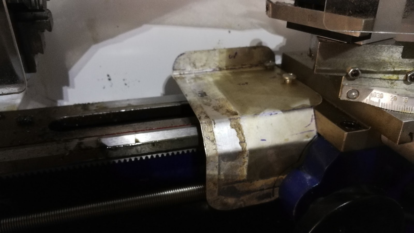
And I have made a sheet aluminium guard to keep the worst of the turnings off the bed ways and leadscrew.


This is about the only useful thing I have used it for so far - I have trued up the tommy bar I filed from scrap...


There's a long list of jobs waiting for it:
  1. Suspension washer
  2. Wheel nut spanner - waiting drawings 
  3. Hub ring spanner
  4. Door knob screws
  5. Oil can spouts
  6. Magneto pinion puller
  7. Handlebar lever spacers
  8. FH brake linkage parts
  9. Front number plate mounts
  10. Push rod tube seal adapters
  11. Chip protector
  12. Tool post stud - waiting material
  13. Damper rods
  14. Carbon steel engine bolts for the SQ4. I want to replace the stainless ones and use some chemical black, to get them back to the original appearance
I've made a new page for the Mini-Lathe, to record details & links relating to lathes, tools and accessories. I'll blog the jobs I do with it here as usual.