Showing posts with label handlebar. Show all posts

Tuesday, 26 May 2026

Model A - girder fork investigation

 I guess that I have been shying away from looking at the girder forks for a while - it occurred to me that I have never dismantled a set of forks like these but having dived straight into it, it's dead easy.

The first job was to make sure the back of the bike was strapped tightly to the lift table and then use the scissor lift to raise the engine a bit. Then I gingerly loosened the front wheel in its clamp and confirmed that everything was stable. 

Pulling the forks about revealed a lot of movement and I made a little video:


There you go - clearly a number of problems there. 

Removing the spindles and replacing them with scrap round bar allowed me to have a look at the links. The part you would call the bottom yoke in a conventional telescopic fork is called the fork crown by Ariel, and the links attached to the crown at the bottom are pretty worn:


Both sides, as you can see. This means the links will need bushing or replacement; the top ones are worse.

Fortunately removing the crown and steering column revealed that indeed there were no balls in the steering head bearings, so that will account for a lot of the movement.

I will probably clean up this area and leave it in factory paint as it is in quite good condition.


The steering head races had two balls left in them. We will clean them up and see how worn they are.


Ariel call this bit the ball head clip - it carries the handlebars and the spindle for the top links. Said spindle was absolutely solid in the clip and I had to resort to the splendid Rothenberger Surefire 2 to warm the grease up and get it to move.


The spindle came out eventually - but look at the state of it. The bike has also been used with the spindles loose which has worn most of the thread away and part of the link too.


The main girder assembly looks pretty good:.


I'll repair these worn areas though - it looks like the mudguard has been loose and has fretted the fork leg. These will build up with weld.


Whilst the girder fork assembly is still a bit contaminated with old grease, I'm quite confident that the spindle bores are good enough.


I spent a while getting all cleaned off the next afternoon. The two races that fit into the frame are chipped but with new balls seem to work ok.


I'm going to replace the spring while I can. You remove these by tapping the end with a hammer and a punch to unwind them from their fixing spiral:


This is the lower fixing - the upper one is part of the main girder.


You can see that the spring has opened up - it must be quite soft.


I rebuilt the forks with the new balls in the steering head to determine how much play I had solely coming from wear in the links and spindles. With these old parts in place, the wheelbase varied 3/8".

I've been in discussion with the Black Ariel spares man for the AOMCC and have some new parts on the way.

Tuesday, 23 September 2025

W/NG - it's coming home?

 It's been a while but I'm hoping that the W/NG will be coming home soon for a few jobs. It will be great to see it, since I've not been on it since August 2023 when I delivered it to Tom's before the 2023 Castle Acre Run with the local VMCC.

To prepare there's a couple of things to do: 

  • Check the tyre pressures 
  • Make sure the fuel tap doesn't leak 
  • Make sure the electrics work 
  • Check if I've got fuel & oil

Son Thomas has already replaced the handlebar grips:


These had all but fallen apart in the couple of years that it's been away. It's getting a new battery - the existing one is dated 2013 and won't take a charge.


Friday, 20 October 2023

FH - nacelle & handlebars

 I'm working on several fronts here, aiming to find problems and clear space so that I can start on the bottom end of the engine. Once that's in, there's polishing and plating, cables and wiring.

The nacelle went on relatively easily, though the trim on the front doesn't fit too well. That will need sorting out:


I planned to fit the instrument panel, mainly to avoid losing the trip reset cable but I found a few problems:
  • the speedo bracket only fits one way, basically because it's too wide. I fitted it by elongating the holes but it would be nicer if I made a new one.
  • the ammeter is one of those - - 0 - + ones, with no numbers. I'm not sure that's correct.
  • the Lucas U39 headlamp switch is damaged where the clip fits - people prise these out and the Bakelite breaks.
On the up side, both the light switch and the speedometer have PVC cables - maybe the whole bike was wired using that stuff.


Next - working through the little bags of screws, I find the grub screw for the steering lock, so that's fitted:


I treated the bike to a nice set of stainless steel handlebars from Draganfly - made in Bungay. The SQ4 has these too and they are very nice.

There's a lot of work to bring the levers up to scratch though!

Wednesday, 11 May 2022

Charlie's Shed - adapting threads

The FH kit came with a lot of original Ariel cables, most of which were pretty rusty but which still had their original adjusters and nipples. The cable layout changed with the advent of the swinging arm bikes, in that the mid-length and gearbox end adjusters moved up to the handlebars for the front brake and clutch. The thing is, most of the handlebars out there use the later 5/16" BSF adjusters, but Ariel used the earlier 1/4" adjusters to the end. Guess what? Levers with 1/4" adjusters are like hen's teeth!

So what to do? after looking at eBay for ages, and noting that Draganfly are out of stock I decided to modify what I had by sleeving the existing 5/16" thread. The issue is that putting a 1/4" thread inside a 5/16" thread leaves very little wall thickness, so the part would be weak. Here's how I set about it:


First job is to turn a bit of scrap brass to the correct OD - 5/16", and put a thread on it - these are BSF threads in these levers, by the way - so it's 5/16" x 22 tpi. Next, we can drill a hole, tapping size for 1/4" BSF, but we won't tap it yet. Next we can try it out in the lever perch and if all is well retain it with some Loctite 263 high strength thread locker:


Next job it to file the ends flush, and tap the hole. Currently I don't have a tap long enough to go all the way through, but it's long enough for the adjuster. Cut the cable slot with a hack saw and a needle file:


Job done!


Wednesday, 15 July 2020

QR50 - Handlebar rework

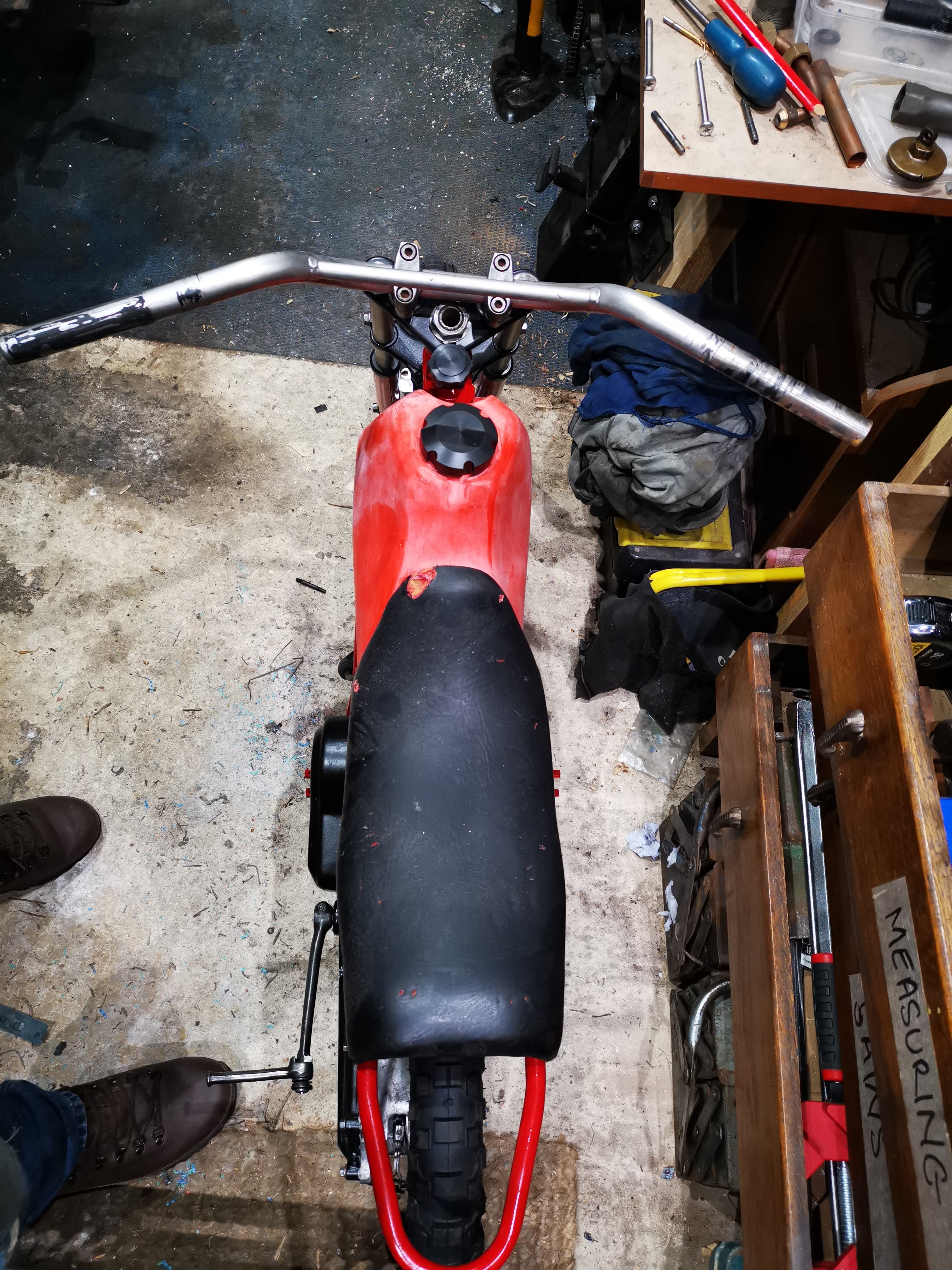
We saw in a previous post how the handlebars that arrived in the QR50 'kit' were very large compared to the original bars - obviously they are normal size bars, but the QR50 bars are designed for small people. The post is here. I made this comparative picture to look at the differences - you can see the relative lengths of the various sections and the substantial difference in the way they are mounted:


What we are going to do is chop them up and reweld them into the proper shape. We start though with the part the grip fits to; the grips, switches and brake lever I have are made for 'pit' bikes and use a smaller diameter bar.
 

I've welded in a pair of new tubes for the grip ends:


The next step is to chop the brace out:


In the first picture, we can see the rise is too high, so we will chop a bit out of the straight section:


With a suitable prep and a supporting tube, it's easy to weld:


One done, one to go:


That's it, all tacked up; levers next.


Now, here's the thing. The QR has a funky CDI unit that requires a wire to be earthed while starting. This is done with a switch on the rear brake lever, and I don't have that - in fact I don't have any levers. I've bought a pit bike set which includes a conventional clutch lever for the left, and a combined run/stop switch, twist grip and front brake lever for the right, and I have a Honda front brake light switch that I bought from eBay.

What I'm going to do is build a lever mount for the rear brake lever which will carry the Honda switch to allow the bike to start with the rear brake on. I've made a few bits - there's a tube to carry the switch, made in the lathe; a tube for the brake cable abutment, also made in the lathe, a 'U' shaped section as the lever mount and another 'U' shaped piece to form a spring loaded lever which will hold the rear brake on while you kick the bike over. 


Some bench work has these fitting together. You might be thinking, 'why is he making all this stuff?'. Well, QR50s are not exactly common - I think most of them went to Australia; bits are not common and when they do come up, they are hellish expensive - so here we are.


Out with the TIG welder:


And trial fit all the bits:


Next, we have to figure out what angle to cut the mounting such that the lever ends up in the right place when it is fitted to the bars, and such that the brake and electrical cables can be fitted and have a reasonable route:


Tack it in place, and then trial assembly:


There we go, all good:


These pictures were taken two years later, but show you how it ended up:


Here's the rear brake lever in it's final form:


You know the really annoying thing? There's something relating to the CDI unit that allows the engine to start whether the rear brake is on or not. I know the switch works, but other than that...

Wednesday, 10 June 2020

QR50 - Handlebar survey

Regular readers will know that the kit of parts did not include an original set of handlebars, which throws up a couple of problems relating to the rear brake lever and the size of the bars themselves. We'll talk about the rear brake lever another time, but if you take a look at these pictures you will see that the bars are much higher and wider than the original equipment:


We can see from the picture below that the original equipment bars rise maybe half the distance from the top yoke to the bottom yoke. On my bike, you can see this rise is almost as much as the full yoke to yoke distance. Reducing this height would mean losing the brace.


The additional width is simply outrageous:


The original bars are actually welded to a sheet metal cradle that bolts to the top yoke - they don't use the clamps my bike has. In these two pictures, you can also see that the ends of the bars are more or less the same length as the seat width - mine are much longer.


The bends above the top yoke are inboard of the stanchions on the original bike, so the centre section between the clamps would have to be reduced. This would mean losing the clamps.


So, there's quite a lot of work to do to get these anywhere near original.

Monday, 19 August 2019

W/NG Handlebar Upgrade

Updated: First published July 2018

Living with the W/NG for a while now - coming up two years, I have realised that I don't like the dropped handlebars as they make you hunch down over the front end. Since the W/NG is great for pootling about the countryside looking at stuff, it needs higher bars - and since I like originality in my bikes I decided to look around for a pair of the original Ariel bars, which are tapered from a 1" central section to 7/8" at the ends.

I was lucky enough  to pick up a set of taper bars from Guy Hovey, of the AOMCC. They looked a bit odd - Guy said they were bent, which they were marginally, and I managed to fix that with a plywood jig and a dose of burning MAPP gas. What was more 'disorientating' at least to the eye was the fact that they had been shortened by an uneven amount at each end, which made them look more bent than they were. Careful measurement with the dividers found that eventually, and I have described how I fixed that in this blog post. It should make a good guide to show others how to repair or extend motorcycle handlebars. You'll note though that the repair is not in a stressed part of the handlebar - it is less than 2" at each end. If the repair had been in a location with a significant bending load, I would have added a solid steel internal spacer to bridge the joint, probably about 2" long.

There's a few pictures a bit further on.

Onward and upward, I found a set of Czech-made levers on eBay, at a good price - good because they were for 1" bars. Not to be deterred and making good use of the mini lathe, I knocked up some brass spacers.

They are made from 1 1/4" brass bar:

Brass bar in the lathe, supported on the revolving centre


Turning the spacers

Drilling to 13 mm

Cutting the 7/8" bore


Parted off from the bar
You will note in these shots that only one of the spacers has both flanges - one has a flange machined off to accommodate the 'web' that the clutch and brake levers mount to.

Marking out for cutting

Almost there

Small flat required to clear the levers

All done

Moving back to the bars, I needed to establish the original length and make the appropriate extensions. Nev Hunter, Australian AOMCC member told me that the end to end dimension was 71.5 cm on his original W/NG bars. Mine was 63...


So, seeking some bent MZ bars from the scrap pile, I cut a couple of sections and squared them up in the lathe. Having squared up the cut ends of my tapered bars with a file, I aligned the two pieces with a piece of copper tube:


I tacked them up in a couple of places with the TIG set before welding.

We call this an autogenous orbital butt weld, when we are welding hydraulic tube together. I held the TIG torch in place and moved the bar to produce a neat peripheral weld:


Gas was set to 5 l/min and the current to 45A.


I used a 1.8 mm electrode, #4 shield. The electrode was fully shrouded and ground to a sharp angle to maximise penetration:


All done
I marked out the length using dividers, measuring inches from a centre point:


These marks show inches from the centre to each end:


I learned that the total length of the tube was 31 inches. Using Nev's information,  I made a square cut at the 15 1/2" mark at each end.


When I'd finished I squared those cut ends up in the vice. Happy with the result, I mounted up all the handlebar equipment to have a look:


Half an hour with some 60 grit emery tape saw them ready for some etch primer:


This is what we are aiming at:


And here we have the finished article:


Today, a year or so after I wrote this post I have updated the handlebar layout to reflect the longer grips the W/NG would have worn: