Showing posts with label rocker. Show all posts

Sunday, 24 November 2024

FH - wear in the valve train

 Last time we were here, I wrote about some wear I detected in the valve train through not being able to set up the valve clearances properly. What I've done now is remove the rocker box again to have a close look at the tappet adjusters and the push rods. 

Removing the push rods and measuring them revealed that the inlet pushrods are correct to the measurements shown in Draganfly's pages of information. Strangely enough the exhaust push rods are actually slightly too short, which is unexpected since I was able to set up these valve clearances easily.


I also measured up the tappet adjusters. I made some posts on the club Facebook page about both the tappet adjusters and the push rods which revealed some useful advice from fellow members. It appears that the tappet adjusters are more or less the correct length, however the later BSA or Triumph adjusters (which are the same length and thread, 5/16" CEI) are provided with hex socket heads and are consequently easier to use. Looking closely at my original Ariel adjusters showed that the square heads were deformed slightly and would not go into the lock nuts, limiting the adjustment available.


I resolved to take the club member's advice, and bought a new set of adjusters and lock nuts.


Further advice from a gentleman who races Ariels had me looking at the extent of the heat treatment of these adjusters. Some of the ones on the market are apparently prone to breaking around the hexagon socket due to over hardening in that area; it appears that the extent of heat treatment on the ones I bought is limited to the area that makes contact with the valve stem, so that should be all right. Hopefully...


Today I fitted the rocker box again, with a longer bolt inside the inlet end. This is a much better approach than the stud and nut that Ariel specified (you will lose the nut down the pushrod tunnel) and is actually a BSA approach to fixing the rocker box shown to me by Steve, a long distance Huntmaster rider. 

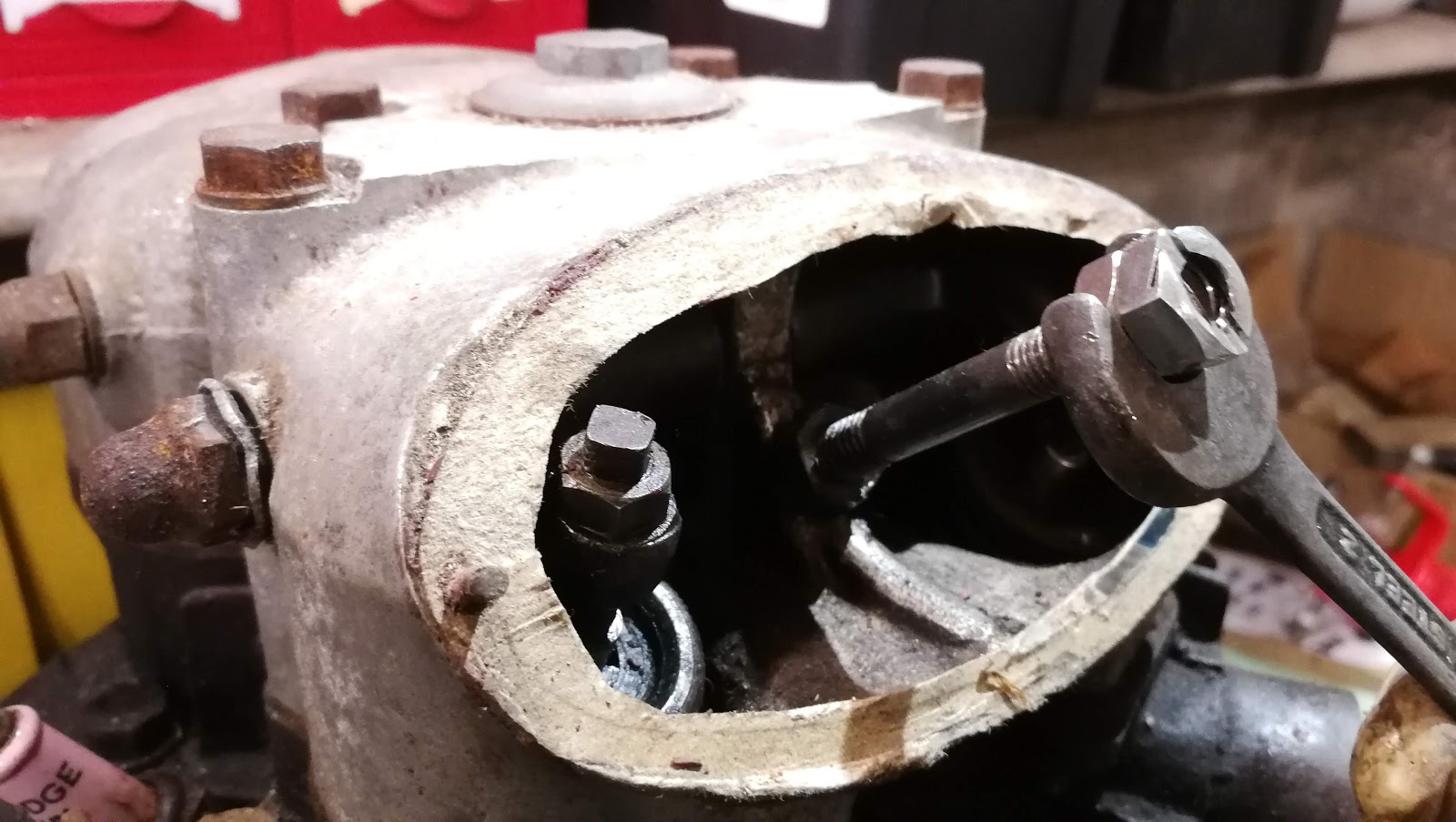
Unfortunately tightening the rocker box bolts revealed that the nuts in the two rear corners could not be fitted with the box fully down. I loosened the main bolts and jacked up the rocker box using the inlet valve adjusters high enough so that I could get the reduced hex nuts in place on the rear corners without losing the pushrod location in the rocker cups.


That done, it was time to pack up for the day but not before I had temporarily fitted the rocker box covers and one of the head steadies. One of the rocker box covers doesn't fit very well due to burring on the locating pins which I'll have to fix later.


Here's a wider view of the engine, with both exhaust pipes temporarily in place:

Next, we can finalise the valve clearances, which are 0.010" for both inlet and exhaust; these new Triumph adjusters need a 1/8" hex key, one of which will have to go in the toolkit. When that's done, we won't need to have the facility to turn the engine easily, so we can close up the gearbox. Before I do that I will fit the pear nipple on the clutch cable; I'll adjust the inner clutch cable length later as I want to replace the handlebar end nipple with a brass one. I'll do the air lever nipple at the same time.

Offline from all this I can replace the dynamo chain and fit the timing cover. Then we can seriously think about first start.

Saturday, 24 August 2024

FH - rocker box refurbishment

With the cylinder head coming on, it’s time to take a look at the rocker box. We won’t be doing too much, as a number of folk have told me how a BSA A10 rocker box fits straight on and is a much better design - but I don’t have one of those.

We’ll start by stripping out the rocker shafts and cleaning the box.

While the lathe is in action, we’ll replace the 5/16" BSW stud that wasn’t holding the cover on - the covers are held on with a special 1/4" CEI sleeve nut. What we need is a stepped stud, like the original in the inlet side but with a 5/16" BSW thread to go in the aluminium casting. Somebody has already recut the thread in the casting to suit the replacement stud.

We'll start with a bit of 5/16" mild steel round bar. Because it's 1/4" in diameter for most of its length we'll need to be careful when we turn it. What we will do is use the travelling steady on the lathe to support the slender quarter inch section as we turn it to size.


 This turns out pretty well especially when we make a finishing cut with a round nose tool. Cutting the 5/16 BSW thread, I've set the die to its largest diameter such that the thread is a little oversize.


This is where the oversized thread pays off - when it's fitted in the box the the stud fits quite tightly and hopefully won't back out.

The next step is to get the box in the cleaning tank for degreasing; we'll then examine it for damage and polish the outside.


Monday, 8 May 2023

W/NG - Dealing with leaks

 Long fast club runs tend to reveals failings in your bike, especially when 'given the beans' by other riders. You know who you are! The oil leaks that have plagued the W/NG really made themselves felt on the 87 mile run around Norfolk that the VMCC Blakeney Run entailed. It was clear that the oil was coming from the top end, but I wasn't sure if it was the decompressor, the rocker box gaskets or the cylinder head bolts.

Having spent some resealing the decompressor recently, I removed the rocker boxes to take a look revealing that the existing aluminium gaskets did not fit at all well:


 I resolved to make some new gaskets.


I made these from Flexitallic pink gasket sheet, which I think is rated to 350°C. I made the gasket a bit wider than the aluminium one, to make sure it covered the whole joint. I sealed it in place with Threebond 1215.

Preliminary testing suggests this has sorted most of the problem, but the decompressor is still weeping a bit. I'll have to add some more shims.

Monday, 24 October 2022

W/NG - fixing oil leaks

 Blatting about at the weekend used a bit of oil, some of it coming from the top end.

I suspect some is coming down the exhaust guide, but some is coming from the rocker shaft end covers. 

I've only recently learnt how to tighten these properly, and I'd damaged one of the fibre washers.

It's all done properly now, with a special screwdriver I made. I've added a small dose of Threebond to the fibre washers as well. 

Thursday, 15 October 2020

W/NG - Assembling and fitting the head

I finished the last post with the cylinder head paint drying, and I went and had a day on the railway which I recorded in this blog post so that now, the paint has been curing for a couple of days.


It's dry but not very hard. I scrape the paint off the gasket faces with a Stanley knife blade, and set about cleaning the bolt holes with a 5/16" plug tap. Apart from this damaged one, they are all in pretty good shape.


Next stop, put the valves in. We know that these fit, because in the last episode we ground them in so this time it is a matter of fitting the valves, Halite washers, spring seats, springs, spring tops and collets. Collets are a bit fiddly to get in, so the best thing to do is put a lump of grease on the stem and then introduce your spring compressor. When you have the spring compressed, fit the collets with a small pair of pliers, tweezers or a chopstick with a bit of grease on the end:


Push them into place with the stick and slowly, gradually, gently release the spring compressor. Tradition tells us to tap the valve stem with a hammer to make sure the collets are seated and the valve/spring assembly is secure.

Next, check the head seal to the barrel. These engines have no head gasket, but the barrel is machined with a spigot which is ground into the head with grinding paste; the area around the spigot is machine a few thousandths deeper so the pressure from the head bolts is born by the spigot alone, sealing the joint. When you are happy that you have a clean joint all the way around the spigot, you can think about putting the head on - but before you do, you need to sort out the pushrod tubes and their seals.

This is the bottom seal - the old, compressed black one and a new one from AOMCC Singles Spares:


Here's the top seal. You see there is a shorter spigot here, which fits around the spigot pointing downwards in the head. I've assembled these dry, with no sealant:


With the pushrod tubes standing in the crankcase, you can drop the head in place, watching the pushrod tubes settle onto the spigots at the top. Next you can drop the 3/8" CEI head bolts in - which I have previously cleaned on the wire wheel. Tighten these down firmly - there is no recommended torque figure. when that's done, the pushrods can go in. When I dismantled the bike, I stored the inlet and exhaust valve gear separately, so I could ensure they all went back in the same place.


Next I took the opportunity to refit the exhaust, with Threebond 1215, and the carburetter - again with Threebond and a new gasket.


Don't forget to put the little caps back on the valve stems:


Next, you can seal the new gaskets (I'm using Draganfly's new aluminium gaskets) and fit the rocker boxes. Be careful with the bolts - three are the same length (about 2 5/8") but one, the one above the pushrod, is longer - 2 7/8". The one shown in this picture is wrong - it's a short one. The danger of this is that you will pull the thread if you overtighten it.


This looks easy doesn't it! What you can't see in this picture is that I had refitted the exhaust rocker box without aligning the rocker in the top of the pushrod. Later, when fitting the decompressor I found it wouldn't work, and I had no compression. What was happening was that the misplaced rocker was holding the valve open, and preventing the eccentric pin on the decompressor reaching the pad on the rocker. Secondly, one of the long rocker box bolts is missing from the exhaust rocker box, so that's two I have to find.

I've now managed to fit both rocker boxes without missing anything out! I've added the rocker oil line, and this time I have fitted a cable tie as shown in the parts book for this bike - it's very unusual to see these fitted.

There is still a rocker box bolt missing (two actually), which I will have to make. I've used the opportunity to introduce some oil into the rocker box through this hole - this is not normally possible, but recall that this hole has a chunk broken out of the head and so provides a passage from the bolt hole into the head and down into the pushrod tube. The objective is to get some oil onto the camshaft.

Sunday, 7 June 2020

W/NG - Smoke and tappets

Having recently retired around the time that the sun came out and the Coronavirus lockdown regulations were loosened here in the UK, the bikes have been seeing a bit of use. This week, I went out with my son on a ride around Coltishall, Norfolk:


That's his Interceptor, which is a fine machine with power low down, a nice seat height and good balance. We tootle around for a bit, testing out the W/NG's new baffles which seem to be cutting the noise down but also seem to have affected the idle - it now dies more readily than it used to.

However, I adjusted quite a lot of play out of the tappets before I left and that reduced the clatter quite a lot, and the bike seems to be going well. I had it up to 60 on the way home, though by the time I stopped there was smoke pouring off the cylinder head and there was quite a lot of oil about - disappointing, as I had resealed the rocker shaft unions which had been weeping for a while. I resealed them discarding the traditional fibre washers for soft aluminium washers, so we will see how that pans out.

So, back in the workshop the spanners are out to have another go at those unions. There's oil everywhere - under the tank, on the mudguard and down tube, all over the timing cover. It has never been this bad.

Then the penny drops - Numpty Spannerman has been at it again, taking stuff to bits and not putting it back correctly. The front rocker cap has gone.


I've often found that I've subconsciously registered some change in engine note or handling performance during a trip, only to realise the cause much later - the senses are very good at picking up small changes. This time, on the way down I had noticed a deepening of the engine note and on arrival there was more oil about in new locations - differently shaped dribbles even.

So that spelled the end for the old brass rocker caps, one lying in a gutter somewhere in Norfolk and the other consigned to the spares box, to be replaced by these fine reproduction examples from the AOMCC Singles Spares scheme. Also shown here are the clips that hold them in place - this is a W/NG only part, and provides some deterrent for the caps to loosen off completely.


Whilst I had the tank off, I took the opportunity to check the tappets again, look at the decompressor seals and check the timing. The tappets and timing were spot on but while I was removing the rocker box bolts to fit the new clips I returned the clutch cable to it's proper route - it's not supposed to go through the tank mount like this:


Here's the decompressor, removed and dismantled:


I've fitted a Dowty washer between the body and the rocker box to seal that joint. Third from the left is the rubber washer, which is rock hard - I fitted a small O ring behind this. O rings are not for use in dynamic sealing applications, but the decompressor rarely moves so I think it will be OK. I've had a quick look for an oil seal that will fit in here but that seal is maybe 2 mm thick - way too thin for an oil seal. Perhaps I will turn a simple carrier to fit a couple of O rings or change the decompressor body to allow an oil seal to fit.


I'd not noticed this weld repair before.

So that was a useful couple of hours work - I had a look at the clutch adjustment as well. These old bikes are so easy to work on.


Saturday, 27 October 2018

Starting the Engine Strip

Inspection starts with a look at the rocker box. Both covers are present, one has it's captive nut, one is missing...

Here's an ugly looking stud and some cornflakes gaskets for general amusement!

All is well at the inlet. The cover stud is seized to the nut and has come out with it:


Removing the exhaust side stud with two 5/16" BSC nuts locked together:


Removing the inspection cover studs, we find one elegant Ariel stud with BSC threads at both ends, one 1/4" for the nut and one 5/16" for the rocker box. The other one, which has no nut is bent and is 5/16" both ends, one BSW, one BSC. Obviously a replacement but a shame, because the thread in the rocker box has been recut BSW. I'll be making a special on the lathe.


A stripped stud retaining (or not) the rocker box at the rear. Steve Carter, an AOMCC member who rides thousands of miles each year on his Huntmasters, uses a bolt here to avoid the worry of losing that nut down the pushrod tunnel:


General view of the head mating surface. All the springs look good at first glance:


Here's the underside of the rocker box:


More cylinder head general views:


Quick shot of the underside of the head. Looks OK, bolts were very tight but came out with some effort:

Bores and pistons. After I took this shot I gave them a quick clean up - the bores are unmarked and have no ridges; pistons have no undersize showing.

These are the dished pistons. Simon Gardiner (AOMCC) tells me that dished are the 6.5:1 standard pistons; if they had been flat-topped, they would be the the export/sports 7.25:1 pistons.

Friday, 26 October 2018

Looking at what we've got...

With the engine on the bench we can have a good look at what we have.


First issue: one of the primary case bolts is broken in the crankcase. We probably won't be using these cases (I have the original crankcases elsewhere, these are not them!) I may not worry about this - but I will probably remove the bolt just for the fun of it. What's worse is the state of those splines:


Nothing untoward here - that hole is for a blanking plug (thanks to Simon Gardiner, AOMCC, for that bit of information)


The sump plate, filter and studs are all missing:


Looks like it has most of it's original screws:


Long magneto bolt:


Unfortunately it appears we have a broken fin on the front of the cylinder head. This may have been caused in a shunt since this is where the head steady bolts on I think.


Bird's eye view of the rocker box:


General views of the engine: