I have been wanting to sort out the dynamo drive for a while - not having it in place leaves a lot of parts laying around on the bench that I want to clear up. It was hindered by having to make a special puller for the dynamo bearings, something that I use infrequently but is very necessary if you're going to rebuild one of these dynamos.
Having finished the puller, I spent a little while turning up a short spacer. For some reason the replacement armature is a little shorter than the original though it fits where it needs to!
And I needed to file up a Woodruff key for the dynamo drive sprocket. It actually took me a long time to get to this place because I had inadvertently assembled the dynamo and fitted it with the dynamo body the wrong way round which caused the sprocket to be something like a half an inch out of line!
Here's the drive in place
That was a chain in amongst the past that came with the bike - it's the correct 3/8 inch pitch but the width is way too much. I'll have to look at Simply Bearings and see if I can find another one, but it really needs to be endless.
You can see here that this over wide chain will rub on the crankcase.
The thickness of the drive sprockets is 1/8" - so that tells us what chain we need - 50 links of 3/8 x 5/32 chain, readily available with soft links from Draganfly:
Following Thursday’s abortive first attempt, I pulled the cases apart again for a look at the big end nuts and to fit another shim to the drive side main bearing.
Roger Gwynn, all round guru, Ariel Hero and founder of Draganfly Motorcycles (without whom us Arielisti would be lost at sea) told me on the AOMCC Forum that the big end nut/crankcase clearance is close in these engines but you don't need to remove much material to avoid a clash. Roger recommended grinding some material from the cases.
What I've done today is make a 1 mm chamfer on the offending edges of the two timing side nuts, so now I know what clearance I need to provide. If I can provide that clearance without modifying components I will be a happy bunny.
Club member Mick suggested that the fact that no bolt thread protruded beyond the nut wasn’t satisfactory, since the locking part of the nut was probably bearing on a reduced (tapered) part of the thread:
I've ordered a new set of nuts, still self locking but to a slightly shallower pattern (still big end nuts, not something nasty) and I'll use these with larger but thinner washers I think. That will guarantee the self locking bit of the nut is on the full diameter of the bolt thread. I’ll probably have to make the washers myself on the lathe.
Meanwhile, adding a 0.1 mm shim to the 0.25 mm shim already there has given me 0.07 mm end float, or about 0.0027”.
This is a short post about a simple thing - hardly worth it you might think, but simple things sometimes trip us up.
I'm working up to building the bottom end, cleaning the crankcases, checking the oilways, things like that. I fitted the oil pickup pipe with a sealer called Permatex No.1, on the advice of some club members - it sets solid and that can be useful in some applications:
Here it is in place. You can also see one of the extended studs I fitted - the sump I am using is considerably thicker than standard. The studs are fitted with Loctite medium strength threadlock.
And another picture from underneath:
This is where it all goes a bit pear shaped. In the next picture you can see that the pickup pipe doesn't fit through the hole in the strainer - one of them is wrong, and this illustrates one of the pitfalls of building old bikes from bits. There is a question over which one is wrong, exacerbated by the knowledge that the strainers fitted to Huntmasters are not the same as those fitted to BSA A10s.
Now, we all know that 'the Huntmaster uses a BSA A10 engine', but actually surprisingly few parts are common. You would think, given that the crank and rods are the same and the crankcase is identical in some areas (not those relating to the timing chest, which is a different shape) that a simple thing like a sump strainer would be common too - in fact, wouldn't the canny design engineer use the bit that was already available in BSA stores? Well, no. And this my friends is perhaps indicative of why our laudable, innovative motorcycle industry went to the wall.
After contacting several experts, it transpires that the sump strainer is indeed different. Given that the strainer was manufactured by SRM (famous for BSA A10 parts) I thought perhaps I had been supplied the wrong one; apparently not. Draganfly Motorcycles, who I bought it from, actually modify the SRM A10 part into a part suitable for the Huntmaster by moving the hole.
We Ariel owners would be lost without them.
It turned out that the pickup pipe was bent - easily fixed when you know what you are aiming at.
With everything now fitting together, I decided to use Permatex again to seal the strainer to the sump plate, on the basis that the original pressed metal sump plate would have been sealed to the gauze strainer somehow as they were supplied under one part number and there is only one gasket listed in the parts book:
I greased the gasket on both sides as this is a service item and I would expect to remove it periodically.
All that remains then is to fit the sump plate. It's got a magnetic trap and this is deliberately oriented away from the pickup pipe to stop the magnet affecting the performance of the ball valve.
A bursting need to achieve something other than walking the dogs in these days of dire weather saw me retreat to a cold garage and put the newly painted luggage carrier and pannier frames, complete with brackets, on the W/NG:
Nearside rear:
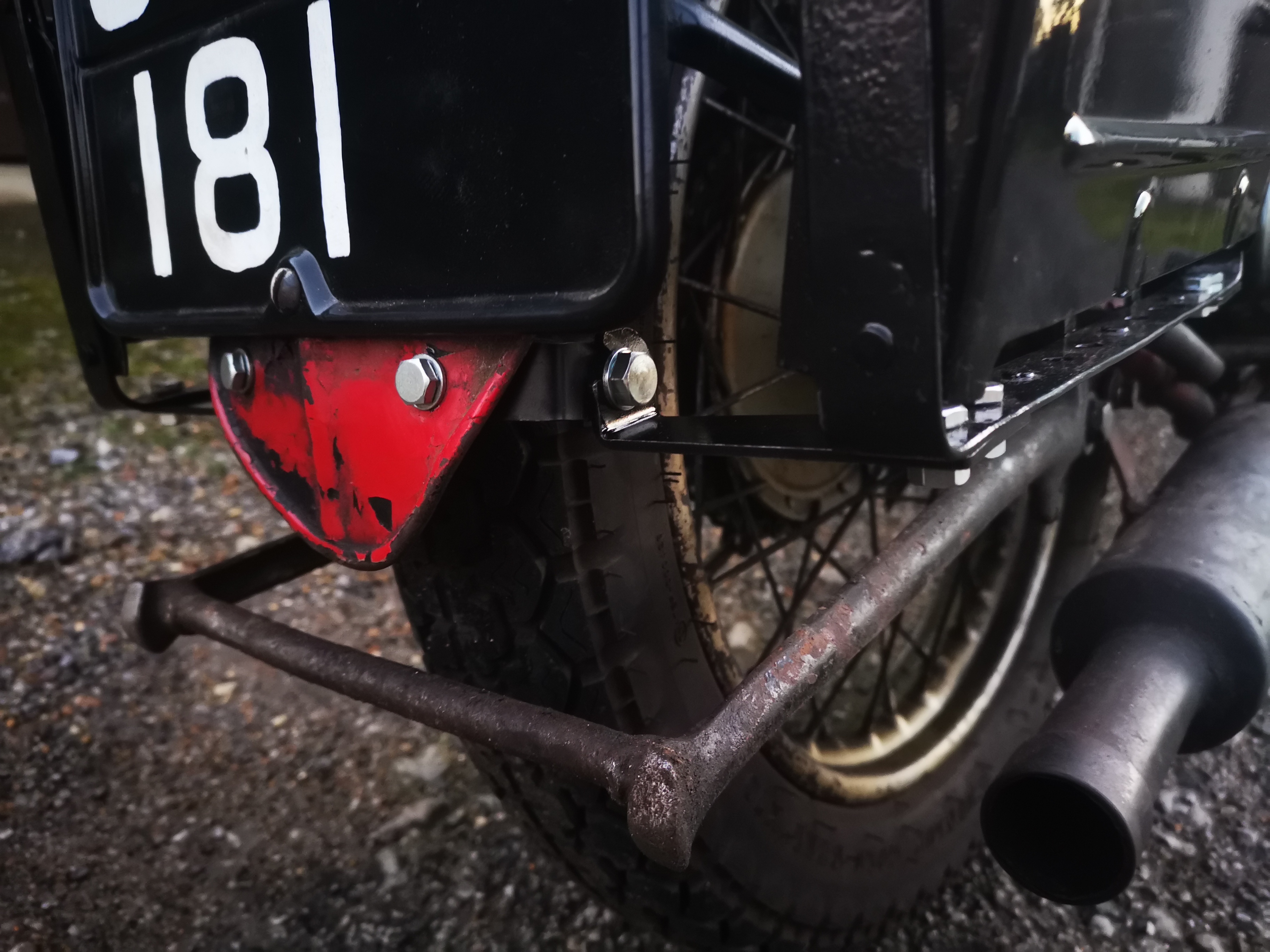
Rear brackets - the stand must be fouling somewhere, it usually comes to rest higher than that:
Front bracket, lightly modified from the Drags one to make it look more like an original:
I think the answer is that the spring lug on the stand is hitting the pannier frame bracket. Here's the offside view:
A bit of railway tomorrow - then I will take some pictures with the bags in place.
I put a bid on this carburetter body (and won the auction!) thinking that I would have a go at sleeving a carburetter back to size, having some fun with my lathe and getting an original carburetter for the W/NG in the process. I know I can more easily go and buy a new 276 from Amal, jetted to suit my bike but where's the fun in that?
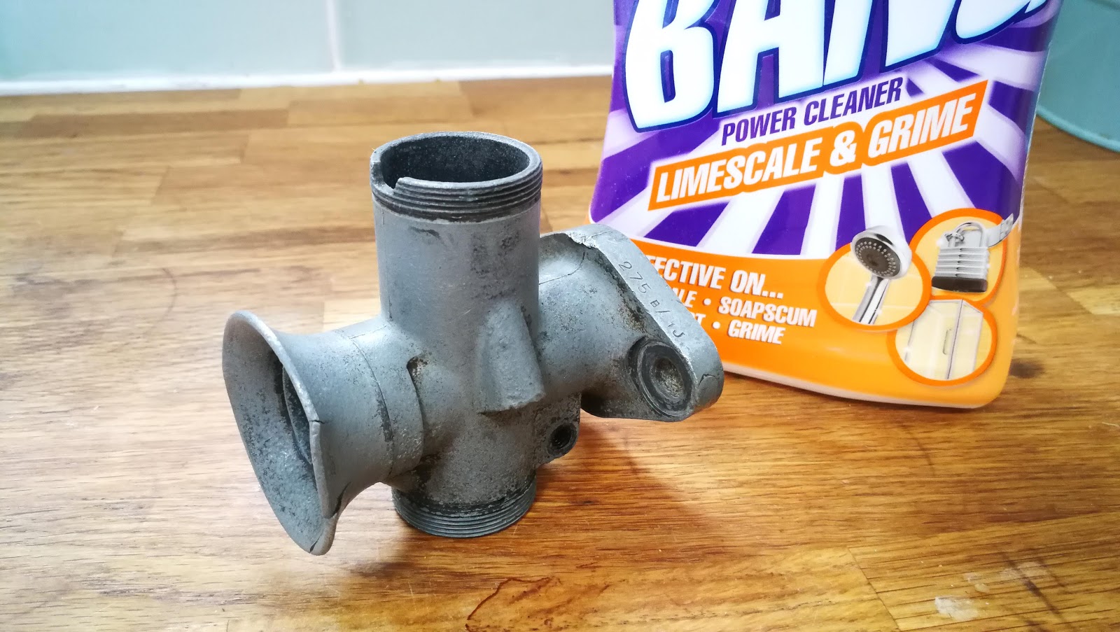
This 275B/1J came up on eBay at a good price, and is perfect for my W/NG:
For less than £20, I have a body, a slide, the jet block and the big union nut. There's a needle and a bent air intake bellmouth. It's all a bit fluffy, but we can attack it like we did the Solex.
It's actually in better shape than the 3HW 276 fitted to my bike, so I will get it up and running and see how it goes. Maybe I'll save the tired 276 for a bit of mini-lathe practice.
It will need an air valve, a mixing chamber top and a top ring, but most of the rest will transfer from the 276. The 5/045 air valves are available from Drags - the top and the ring might be more difficult...
Now to clean it up. With the bottom cap in the vice, we can use a large tube through the bore to provide some gentle leverage after the Plus-Gas has done it's job:
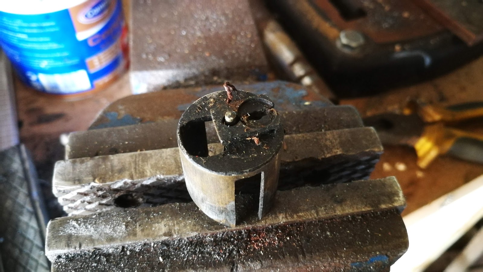
This is the first time I have seen the needle held in place with a bit of wire...
It's interesting how these things wear. That slide is nominally 1" OD; at the bottom, it's close to that:
It's very worn at the top, where the differential pressure pushes the slide against the body. It's about 0.965" here:
The top of the carburetter body is close to nominal:
The nations favourite carburetter cleaner. It's the fact that you are not supposed to use it on aluminium which makes it attractive - it's good at removing zinc oxides too, as well as old petrol deposits.
The brush on the right is called a 'file card' - it's for cleaning debris out of file teeth. It's also very good at cleaning threads in soft carburetter bodies:
Talking of threads, the throttle stop and air screw threads are 2 BA and are easily cleaned with a suitable plug tap. Don't force a taper tap into the air screw port though, or you will destroy the needle seat.
All the bits I have:
Rubbing the flange joint on some 120 grit sandpaper on a glass plate shows it is in pretty good shape:
Eventually I got a top and a threaded ring from eBay and I have just ordered a slide and an air valve from Drags, at vast cost. Here's the top ring and the top, of which both cable adjuster threads are intact. I'm happy about that; but not so much about the ding in the choke adjuster thread, which means the adjuster won't go in.
These threads are a little unusual - they are 7/32" x 40 tpi, which is a ME (Model Engineer's) series thread. These are a fine Whitworth form, and fortunately the taps and dies are readily available fromt the excellent Tracy Tools:
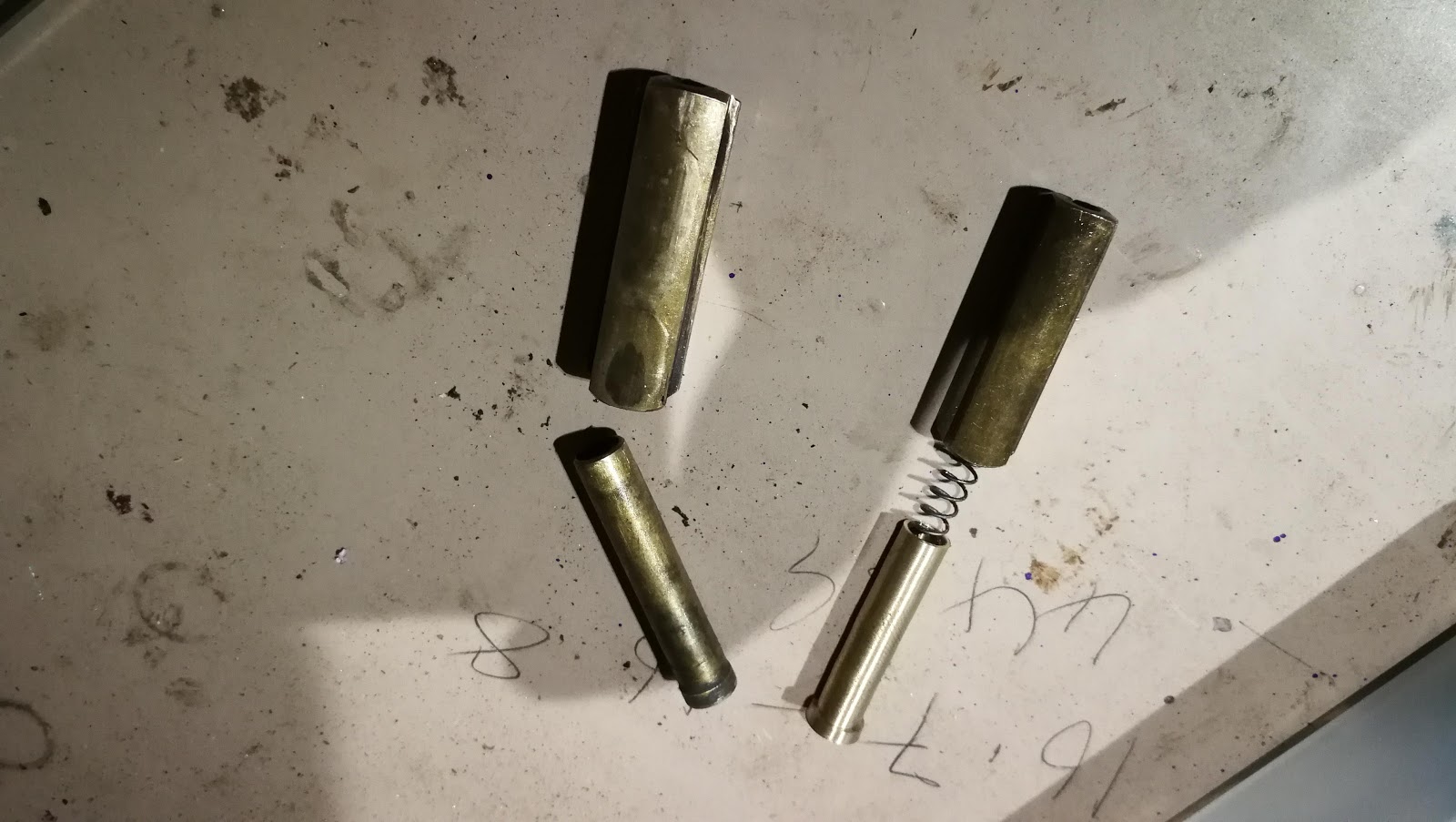
Next, while assembling the slide and choke into the carburetter top, I realise that the air valve guide is missing. I can turn that up from a bit of 10 mm brass round bar I have in stock - it's 6 mm on the OD, 7.6 mm where it goes into the top, and the spring is 4 mm OD. I drilled the ID 4.5 mm and then decided to open that up to 5 mm to ensure the spring does not bind.
Here's the air valve and guide from a 276, alongside the air valve for the 275 and the new guide I made:
Works beautifully, so it is on to reassembly.
Close observation of the parts diagram showed that the throttle slide has a split pin fitted to retain the cable. I've never seen that before:
I needed to shorten the cables by about 1/4", but other than that it's all back together. The fuel tap has a solid but old filter, and I have replaced the corks in both plungers; the return plunger has a new screw as well. Fuel tap repairs are shown in the first half of this post.
No man shall have worn mainshaft bearings. Any man found with worn mainshaft bearings spends a night in the box!
No man shall be missing his kickstart stop. Any man found missing his kickstart stop spends a night in the box!
No man shall forget his lubricant. Any man found forgetting his lubricant spends a night in the box!
One of my favourite films, Cool Hand Luke.
Talking of spending a night in the box, the engine is going to be ready next week and I need to have the gearbox out & cleaned because if I know myself at all I'm not going to want to tear Amelia apart anytime soon, when the bottom end is back in.
So, I've been looking at Mr. Waller's book and I need to record what I'm doing with the gearbox. There doesn't appear to be a manual for the BA, so perhaps we can write one.
Many machines used Burman gearboxes, going back to pre-war years including Ariel, AJS & Matchless, Panther & Vincent. Many of these manufacturers used the GB gearbox with the enclosed clutch arm, and there is some material out there on these boxes. This text is predominantly about the earlier BA box fitted to my Square Four, which shares much of it's internals with the GB, and indeed the GB was derived from it.The gearbox which is the subject of this article is a 1951 BA from a Mk1 Ariel Square Four. There's an excellent video, by Alan Moore of the AOMCC, showing how the gearbox works:
Getting Access - Removing the Gearbox
Remove the clutch cable by loosening the adjuster and disconnecting the cable nipple from the clutch operating arm on the gearbox outer cover. If you have the rubber boot fitted over the arm, draw this back over the arm to expose the nipple.
Just imagine how that would have been handled in a Carry-On film. You can almost hear Sid laugh.
Speedo Cable Screw - don't lose it!
The speedo cable is removed from the end of the gearbox by removing the screw on the outer casing beneath the cable. Put it back in once the cable is removed so you don't lose it.
Loosen the bolts securing the kick start lever and the gear lever. I leave the levers in place since it gives you something to hold when you remove the gearbox.
Remove the clutch cover, slacken and remove the spring screws and remove the plates. You now have access to the clutch centre tab washer which you can knock back, followed by the nut and the clutch centre. Next, drain the primary case and take out all the screws. Split the primary chain and put it in a bag to keep it clean. Now you can knock back the tab washer (in six places) securing the clutch basket screws. Remove the screws. When you lift the clutch basket away, arrange a plastic ping meal container underneath to catch the needle rollers within the centre bearing. Hopefully they won't all fall out. There are 12 of them.
On a Square Four, take off the oil tank and battery carrier to give greater accessibility to the top and bottom clamping and swivel bolts. On my W/NG you can get to the top bolts without removing the oil tank, but it's still easier if the tank is not there.
Lastly, remove the two rear chain guards and the rear half of the primary case. You can now see, and hopefully you will clean the gearbox.
Complete, vice mounted Burman BA
The gearbox is now ready to be removed from the frame. Loosen all rear engine plate bolts and the gearbox adjuster and allow the plates sufficient slackness to enable the gearbox to be lifted out towards the offside. Have a rest. I know your pride & joy looks like a basket case again doesn't it!
Clamp the gearbox in a vice by way of the bottom swivel lug and remove the nuts securing the outer end-cover, which can then be pulled away complete with the kickstarter and foot-change mechanism. This is what you will see:
CP Gearbox Kickstart & Selector Mechanism
We'll look at these bits later, or you can skip to the bottom of the text and look at them now, which is what I did!
An exploded gearbox. I hope his book is out of copyright. The gearbox is of course upside down...
Dismantling the Gearbox Internal Mechanism
The kickstart pinion ratchet & pinion
This operation can begin by unscrewing the hexagon nut on the end of the mainshaft and taking off the kick-starter driving ratchet, ratchet pinion, distance sleeve and short coil spring.
These parts require checking for wear, together with the kick-starter quadrant which was removed with the outer end-cover. You need to make sure that the teeth on the ratchet nut (item 41) and the driving ratchet (item 42) are nice and sharp, and not worn. You'll see them in a picture somewhere hereabouts, looking nicely unworn.
The mainshaft nut is a bit mangled though, looks like it has been in a scrap with Mr. Chisel & Mr. Hammer.
The, um, Key to Fig 33. Sorry Mr. Waller.
If the first few teeth of the quadrant are "burred," these should be ground down to give a clean engaging action with the ratchet, but a new part is, of course, advisable. Note that the first 'tooth' is typically ground off, which enables engagement with the pinion in the first few degrees of movement.
Kickstart quadrant. Perfect condition.
Remove the inner half gear-cover from the main casing, taking note of the twelve hardened rollers which form the bearing for the gearbox camshaft. Those of you with W/NGs will note that this roller-race has been replaced with a plain bush. Next remove the slotted screwed plug at the base of the main casing and pull out the pawl spring. Pull out the mainshaft from the clutch side and then remove the layshaft with gears and operating forks as a complete assembly. This is not difficult, but to make it easier you can remove the mainshaft & layshaft third gears before you take the whole cluster out (items 15 and 45 in the exploded view). You can put them back separately too. Saves you dropping them on the floor and spending the rest of the evening in tears.
Inspecting Internals for Wear
The pinions and operating forks should be carefully examined, as should the layshaft and mainshaft. Check for wear on the fork operating faces and renew if at all grooved. Note the order of assembly on the camshaft and that the longer of the two forks is for operating the sliding gear clutch on the layshaft. Remove the split pins retaining the dowel in each fork and remove the dowel. Inspect the dowel for wear, which will appear as flats worn on the sides. Replace the dowel using new split pins, cutting them short & bending the legs outward. Grease the pins and the slots before you reassemble the camshaft.
Forks. Beautiful. Clean. Square. Lucky boy.
Burman gear pinions are not case-hardened, but being made from oil-toughened nickel-chrome steel, are hard enough to give strength and wearing quality without the risk of frequent fracture, which is more relative to gears which have been case-hardened and treated. Gear pinions very seldom call for replacement, unless through some reason a fractured tooth has occurred. Of course, we are looking at gears that may have been in service for many more years than perhaps Mr. Waller might have imagined, so we might look more closely at our teeth. Always pays to take care of your teeth.
So what are we looking for? ISO 10825 lists a number of failure modes for gear teeth:
surface disturbances such as wear, corrosion or overheating
scuffing, which is the transfer of material from one surface to another, under load
surface fatigue, such as pitting, spalling or flaking
fissures & cracks
tooth breakage
Fortunately, examination of the gears revealed no damage and very little wear. Machining marks were evident in some areas.
George had poor teeth...
If the gearbox has been long in service it is advisable to check both the layshaft and mainshaft spindles between lathe centres and using a clock-dial gauge.
If either shaft shows bending to have taken place and this to exceed 0.005 in., a renewal is advised. Test the shafts in their respective bearings or bushes and note that a clearance wear of 0.005 in. - 0.007 in. is permissible before renewal. The driving gear and sprocket, having been left in position in the gearbox shell, should be tested for clearance, both internally and externally, and if the centre bushes show a clearance exceeding 0.006 in. - 0.007 in. when tested with the mainshaft inserted, fit new ones.
Driving-Gear Bushes
Two are fitted with a centre space for grease deposit between the two and are a tight press fit and require reaming after fitting to give a shaft clearance of at least 0.0015 in - 0.002 in.
The contents of my box
To remove the driving gear from the casing the sprocket large locknut must be unscrewed. Some models have a special lock-washer securing the nut, whilst others incorporate the system of punching the inner edge of the nut into one or more of the splines of the driving-gear shank. Knock out, pry out or drill out the elements of the lock washer that are retaining the nut, and proceed with removing the sprocket.
To remove the sprocket, Mr. Waller says: To hold the gear and sprocket from turning, a very useful tool can be made up and used as follows. Obtain a scrap mainshaft and grind two flats on the thick end which carries the clutch race . Fix this shaft in the vice by gripping the flats. Take the mainshaft sliding gear and place on the splined shaft with the large pinion uppermost. Next invert the gearbox case over the shaft and engage the sliding-gear pinion with the driving gear.
That method is all well & good when there are a plentiful supply of old mainshafts knocking around, but I don't think today I or anyone else will be destroying precious spares in this cavalier fashion. My alternative starts with removing the mainshaft, and inverting the whole box so that the sprocket nut can be gripped in the jaws of your vice. Then, take a large Stilson wrench/Monkey wrench/pipe wrench, and open it up as wide as you can. Use the Stilson to grip opposing teeth on opposite sides of the sprocket and turn the whole sprocket, which the vice grips the nut. You might need a tube or something to increase leverage - it will be tight. It's a normal RH thread, so when it won't come undone don't think you are tightening it!
Shh don't tell anyone, but this is a Bantam clutch puller!
Undo it using this method until it is free to turn, but don't forget that the box is supported on that nut. As soon as the nut is undone the box will fall on the floor if you don't watch it! Take it out of the vice and finish removing the nut with the box safe on the bench. The driving gear can pushed into the case for removal, when you strip the internals out. The sprocket can be stiff too. A puller will fix that easily.
Gearbox Sleeve Gear Oil Seal
Seals in situ
During the 1948 season, Burman introduced a self-adjusting oil-seal to be fitted next to the main driving-gear ball bearing. The idea was to convert the gearbox to "all oil" lubrication from the grease or grease/oil mix used previously; although the seal was effective in preventing leakage at the bearing end of the box, there was considerable "weepage" elsewhere.
With a seal fitted it is advisable to use a fifty-fifty mixture of oil and grease as a lubricant and "top up" with a grease gun filled with such a mixture.
The oil seal can be obtained and incorporated on any Burman four-speed gearbox, Type "BA" and Type "CP ". The seal fits with a thin steel gland washer on either side, immediately behind but after fitting the driving-gear bearing (see Part No. 25, Fig. 33). The seal components are shown in picture nearby.
Check the Main Ball Bearing and Bushes
The driving-gear ball bearing is easily pressed out of the housing after removal of the circlip and dust-cover, and the oil seal if it is fitted.
Wash out the bearing and check inner and outer races for pitting and wear. While you are at it, wash out the mainshaft ball bearing from the kickstart end and inspect that too
If bearing shows any signs of wear and "shake" renewal is advised. A worn bearing will cause gears jumping out as well as undue noise. Mine were both loose & showed a fair bit of play once clean - unwashed, they were just gritty & hard to move.
The layshaft spindle bush and camshaft bush fitted into the gearbox case should be examined. These bushes have a flanged-face fitting and are pressed into position.
BA Gearbox Sleeve Gear Seal Components
All the tolerances, plus the actual dimensions of the bushes and shafts from my box are on the Engine & Gearbox Tolerances page within this blog. You'll notice that my bushes are all on the upper end of acceptable wear, but considering that this machine will doubtless be used for leisure pursuits we will not replace the bushes this time.
If the camshaft bush flange is worn the shaft can take up a floating action due to excessive end-play, and as the operating forks are located on the shaft this float will readily cause the forks to over-travel with the sliding gears and disengage them whilst under load. A temporary repair can be effected by placing a hardened shim or washer on the end of the camshaft to compensate for the worn flange, taking care to leave at least 0.001 in. - 0.002 in. end-play.
The coil springs and their housing
After ensuring that all gear pinions and shafts are in good condition for further service, preparation should be made for reassembling the main gearbox. We will however review & inspect the gearchange & kickstart mechanisms first.
The Gearchange Mechanism
The foot gear-change mechanism is of the positive type and allows only one gear at a time to be engaged by one movement only of the pedal either way. Apart from accidental damage, the only parts requiring replacement due to wear and tear over a long period are the two main coil springs and the two pawl coil springs positioned in the alloy spring-box, and the ratchet and quadrant pawl.
Pawl and his teeth. Actually very good
The ratchet and pawl should be closely examined for any sign of wear at the engaging points and, although a temporary repair can be made by "stoning" up, these parts should be replaced if they appear to be unduly worn. Check the tightness of the three rivets securing the ratchet and quadrant to the sector. Any slackness of this assembly will cause trouble in gear engagement and, resultant jumping out of mesh will occur. You'll see the three rivets in the adjacent picture - two round rivet heads on the arc with the gear teeth - the third is just visible as a circular mark on the pawl ratchet. This rivet is countersunk this side. Note that in the same shot you can see the timing mark on the arc with the gear teeth - the small punched 'O'.
Three rivets & a ratchet
The Kick-starter
Hopefully you remembered to inspect the kickstarter quadrant when you took it out - if not, clean it and do it now. When you have it clean, pay close attention to the splines for the kickstart lever. If these look worn (i.e. they are not distinct sharp splines with parallel sides) go and find a new shaft. The shaft can be pressed out of the quadrant if need be.
The quadrant and ratchet having been examined or replaced, attention should be given to the kick-starter lever return spring. Ensure that the spring is strong enough to return the lever and pedal to the vertical position after being depressed. A weak spring can have its tension increased by rewinding a further one or two turns, or you could seek out a new one, or, if you fancy playing with your Rothenberger Superfire 2 you could reharden & temper the old one. No guarantees though, this is tricky work!
Kickstart Quadrant Stop (top left)
When refitting, do not wind the spring up solid, but only sufficient to throw the lever and pedal sharply to the normal vertical position. The inner end of the spring fits into one of the slots on the kick-starter shaft immediately behind the quadrant, and the outer end to a peg provided in the gearbox cover. The correct way for fitting the spring is for it to be located on the shaft with the coils running clockwise from the centre. If fitted the reverse way, the pedal will be thrown to the lowest position instead of to the top of the stroke. The gearbox is fitted with a stop for the kickstart quadrant, which is akin to a Metalastik bush (a steel ring with a rubber centre) fitted over a peg, which is in turn a press fit in the middle casing. AOMCC wisdom suggests that it's installation restricts the kickstart movement some 20-30 degrees.
Reassembling Gearbox
Assemble the cluster on the bench
This is really a reversal of the dismantling operation, said Mr Haynes. Before you start however, prepare all the parts. Make sure everything, including your bench, is really clean. Clean off all that nasty red hermetite the previous bodger smeared everywhere. Clean the oxide off the cases with a wire brush, make it nice and shiny with a dose of elbow grease and save yourself a trip to the blaster. Make any repairs you need to make to the alloy parts of the case - repair that broken clutch cable lug, replace the missing kick start stop.
New kickstart stop peg
Actually I cheated a bit here. I have never tried aluminium welding (though there is an excellent site at www.mig-welding.co.ukto help you), so to deal with the broken clutch cable lug I bought a new middle casing - but this one had no kickstart stop. You might remember it from this post. Now, normally these are a press fit in the middle case, but mine was missing and the hole mis-shapen. The best option I had was to recut the hole with a 1/2" tap, and the only one I had was 20TPI. I had intended to make a new stop peg from a 1/2" BSC bolt, but since I couldn't find one I had to make a new one from 1/2" round bar, 1 1/2" long, and threaded 1/2" BSC for 1" of its length. I tapped the hole on the case, and cut a slot for a screwdriver in the threaded end of the stop to wind it in. I will secure it with Loctite when I have assembled the rest of the box.
Kickstart stop peg in place
Then replace any bushes that are too tired and ream them to size, not forgetting the tiny bush for the clutch arm. These like most bushes are a press fit in the clutch arm lug on the outer case. Remove them by pushing them out wit the new bush. with the aid of a small bolt (M5 fits neatly) drawing the old bush into a small socket. Clean out the shavings. Replace any missing Welch plugs from the drive sprocket end of the case. These are really easy to make from sheet steel, formed hot with a ball pein hammer in an old socket of a suitable size and deserve a post of their own, since I am running out of space for pictures here!
Lastly, fit the new ball bearings. This is made a lot easier if you leave the bearings in the freezer while you have your dinner. Make sure the seats for the bearings are spotless - you don't want any grit or swarf preventing the bearing from going into the proper position, otherwise they will not be supported properly and you won't get the oil seals in - there is not much space in the large bearing housing for the bearing, seal and the spacer discs. Heat each case with the trusty hot air gun and drop the cold bearings in, seating them with a suitable drift - don't touch the balls or the inner race with your drift, punch or hammer! A cold bearing in a hot case won't need much force, if any. Put a few drops of a bearing retainer (I use Loctite 603) around the outer race.
Now we can begin assembling the box.
Note the correct order of the driving-gear ball bearing, retaining rings, felt washer, etc. and assemble those parts. Grease the bearing as it goes in, and the oil seal if you have one and fit the spacer into it. Insert driving gear in the new bearing, fit the sprocket, the lock washer and do up the nut. You can tighten it but don't bend the lockwasher yet, until we are sure it doesn't need to come off again. I like to leave the nut loose until the box is fully assembled & tested, since it is a pain to tighten. You don't want to do it twice.
Knackered clutch arm bush
Make up the mainshaft gears, layshaft assembly, camshaft and operating forks into a complete sub-assembly, and insert this into the gearbox case, locating the layshaft and camshaft spindles in their respective bushings. It is easier if the camshaft pawl is off whilst replacing the cluster. Insert the mainshaft from the driving-side and pass it through the mainshaft sliding gear. Wiggle it a bit to get it through the splines.
Wiggle the cluster into the case
Fit the remaining third mainshaft gear on to the shaft end. Check the proper position of the camshaft pawl and refit it, followed by the pawl spring and plug. Leave the plug a bit loose until you have the end cover on - it makes it easier to test for each gear when you are rotating the camshaft by hand.
Fill the roller groove at the end of the camshaft with grease, and place the twelve camshaft hardened rollers (where fitted) in the groove, sticking them in the grease, and fit the gearbox inner cover.
Use Wellseal on the cover - there is no gasket. Nip up the 1/4" BSW nuts securely. Test mainshaft for end-play which should be 1/64 in. - 1/32 in. If end-play is excessive, this can be reduced by fitting a slightly longer ratchet pinion steel bush on which the kick-starter pinion and small coil spring fit. Another method for reducing end-play is to countersink the inner face of the shaft nut to allow it to project over the shoulder on the shaft end and so push the ratchet further along the shaft.
Refit kick-starter ratchet assembly and tighten mainshaft and nut. Turn the mainshaft to make certain it is free - I have nipped the kickstart pawl spring behind it's sleeve, which isn't obvious and puts a side load on both rolling bearings.
Timing Must be Checked
Add the 3rd gear pinions
Before you go any further, make sure you can select all the gears. Turn the camshaft using the quadrant - it can be a little stiff, but turn the mainshaft to help it along. You don't want to finish assembling the box only to find something amiss. Tighten the pawl spring plug when you are done. Dave Pitt from the AOMCC says:
"Going anticlockwise the 0 on the cam gear is at about 2 o'clock in 4th, 11 o'clock in 3rd, 8 o'clock in 2nd, between 5 & 6 in detented neutral, and about 4 o'clock in 1st. You can find an undetented neutral between 2nd and 3rd, and 3rd and 4th. The 0's align in undetented neutral between 2nd and 3rd."
Note that when finally fitting the foot-change assembly the quadrant and small gear pinion on the camshaft must be correctly "timed" or meshed, otherwise incorrect positioning of gears will result. The quadrant and pinion are marked with distinctive timing dots (the stamped 'O's) and these must be intermeshed when the gears are in the neutral position before finally bolting up the outer gearbox end cover. As Dave Pitt says, note that the 'neutral' referred to here is a false neutral, not detented by the pawl, between 2nd & 3rd, and is not the true neutral. The true neutral is a detented position on the camshaft between 1st & 2nd.
CP Gearbox with stamped 'O's' aligned
Gear Indicator
Refit the end cover - use Wellseal again on the joint, there is no gasket. Whilst the gearbox is still in the vice, make sure you can get all the gears. and make sure the kickstart returns the lever smartly to the top of its stroke.
You can now tighten the sprocket nut - fit an old clutch centre, with a bar through the studs and you will be able to tighten the sprocket nut sufficiently. When you have finished heaving this about, you can refit the two gear indicator pointers and the clutch lever and it's adjusters.
A gearbox in a frame
Install the complete gearbox back in the frame. Fit the gear lever, kick start lever, and the clutch cable. Then check the engine plate nuts once more and fill the gearbox with grease/oil mix, enjoying the unprecedented access to the filler cap. The end cover as well as, of course, the main gearbox case should be nearly filled with any of the makers' recommended brands of grease mixed 50/50 with oil, or a self-leveling grease. Quantity required is about 600 ml. Do it up and re-fit the oil tank if you removed it. Fit the speedo cable, noting that it goes right down in the hole and that the screw slides into the annular groove in the cable end. If you don't get it in far enough, the cable inner appears mysteriously too short, but will intermittently drive the speedo...
Now you get to go around the other side and put the clutch back together!