Showing posts with label tap. Show all posts

Tuesday, 3 October 2023

FH - Preparing for assembly

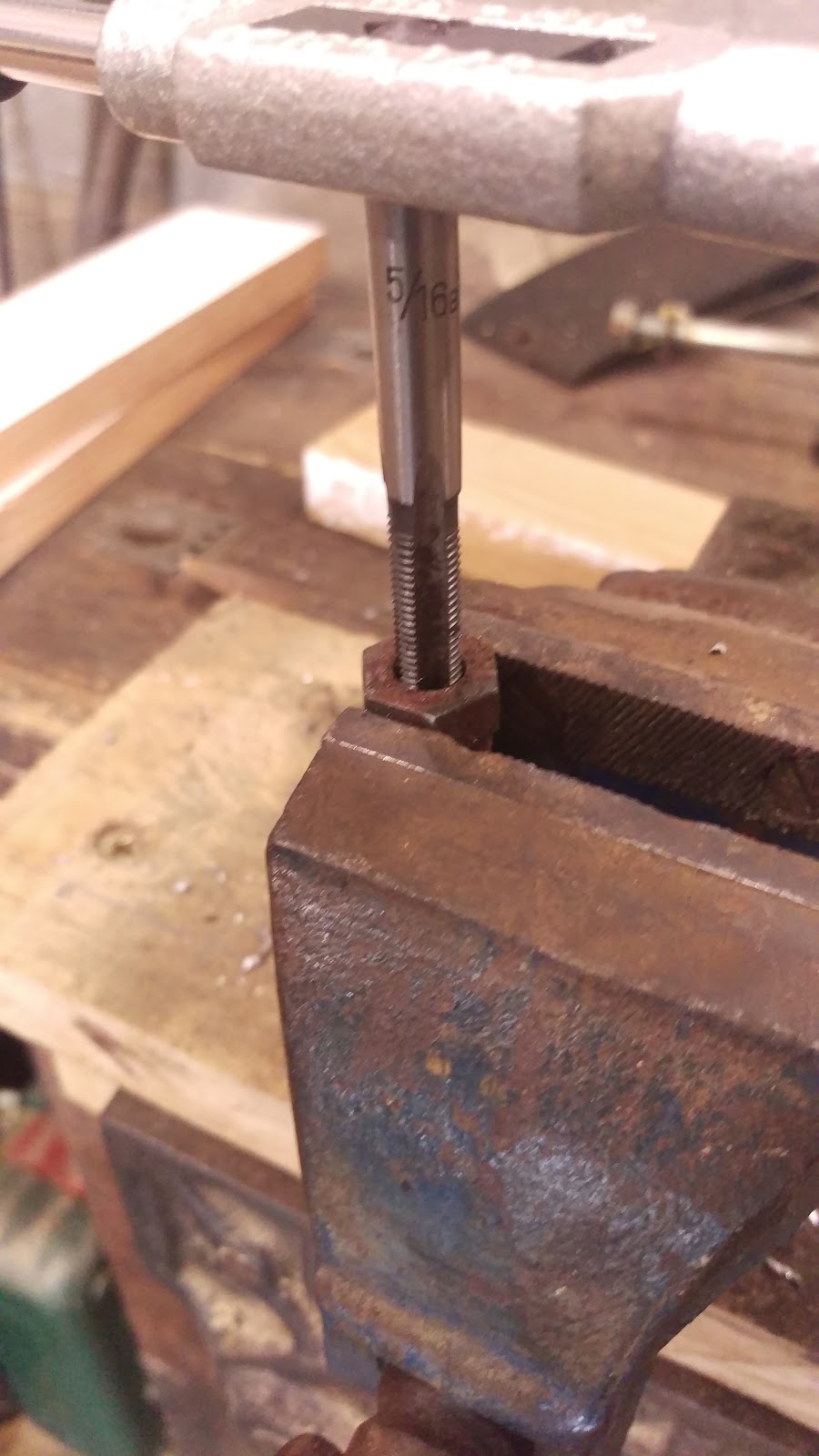
 One of the nice things that arise from a dedication to one make, one era or perhaps just motorcycles manufactured in one country is a collection of specialist tools. Today, I'm quietly cleaning paint out of the threaded holes in the frame, yokes and swinging arm with CEI taps, while I wait for other bits to arrive and for the rest of the painting to be finished:

The fork stanchions have arrived:

And we have new seal holders, seals and progressive fork springs:

Thursday, 18 March 2021

Model A - repairing threads

It's a wet day here in Norfolk, and I have some domestic stuff to do in the workshop so while I'm at it I might get distracted...

I'm looking at the workshop layout with a view to getting a bike lift in there, so I have shuffled them around and the Model A happens to be accessible, so we will have a look at a couple of loose ends. The front mudguard has been hanging off for a while (and still is) because there are a couple of dubious threads in the forks - one, a broken bolt, and then two other threads that are just fouled.

Here's the broken one - I have put a 1/8" hole through this broken 1/4" bolt, to see if it will come out with an Easy-Out. They never do, but I have to drill the hole anyway!


Of course, it didn't come out and I moved through the drills until I was one size under tapping size for 1/4" CEI. I then applied the 1/4" CEI taper tap and used it to clear the thread - it moved the remains of the bolt:


Next stop, same problem at the back. I made the mudguard & rack fasteners a while ago and could only fit one side, because I found someone had broken one of the 3/8" bolts in the frame lug, drilled and tapped it something like 5/16" and put a new bolt in. Today, I removed the broken 3/8" stump using a diamond burr in the Dremel and chasing out with a 3/8" CEI taper tap, so this shot shows it all back together with the stand spring fitted at last:


I also took the opportunity to chase out the chain adjuster threads. Grovelling about on the floor makes me realise that a hydraulic lift would be a nice addition to the workshop!

Back at the front, I now have both sides of the mudguard stay fitted - to cut the mudguard, I need the centre bracket and the front stand fitting - unfortunately I have run out of 5/16" screws, so that's the next job.


Comparing the next picture with my picture above, you can see I have the mudguard stay too far forward:


Tuesday, 13 October 2020

W/NG - Interlude to engine assembly: fitting the bash plate

I've had the bash plate for the W/NG sitting around for over two years. I bought it on eBay, but I have never fitted it because they are an absolute pain to get on. Here it is, in original paint:


The sump guard mounts to the front lower engine mounts like this, and this is the reason it is a bit of a pain to fit. That stud retains the engine to the engine plates and the lower frame rails, and of course the engine plates tie the upper and lower frame tubes together. Secondly, the stud has to come right out to get the sump guard on. The problem comes because the frame will spring open when you take the stud out and therefore to get the stud in you need to lift the frame rails using the bike lift.


The rear fits in a single 5/16" CEI hole in this cross member, between the engine and gearbox. This hole has been peppered with road debris for years, so it needs cleaning out with a tap.


Once it's clean, you can retain the rear of the sump guard with a single hex screw and washer:

Sunday, 6 September 2015

Retrieving broken studs & screws

I've been meaning to take a few hours to write up the removal of a couple of broken screws.

These two examples are both parts of my Huntmaster - One is a fork clamp bolt, in which the screw retaining the headlamp casquette has become seized in the past and broken by someone; the other is a engine mount spacer, which in these bikes is provided with a small 2 BA lug to retain a pressed metal cover, which enhances the appearance of the engine mount and prevents it getting full of road dirt. Of course, in this exposed position these little screws seize solid. I managed to get one out, aided by some prehistoric oil leak, but the other was dry as a bone and broke as I worked it.

So the process for fixing this kind of problem is this:

Put the part solidly in the vice, and file the broken bolt flat; then centre punch the broken fastener right in the centre.

File the broken screw flat

Using a small drill, make a pilot hole right through the broken fastener. As you start it, make sure it's still on-centre

Pilot hole in the old 2 BA engine mount screw

Using a larger drill, open the hole out until you are approaching the minor diameter of the thread
Small pilot drill hole in the old screw

Continue drilling out the old screw
Try an Easy-Out in the hole, selecting the largest one possible that will bite in the hole. Turn it gently with a tap wrench. Don't force it - if you break it in the hole you are in real trouble.

Small Easy-Out
If you don't have any success with an easy-out (and I can't remember when one worked for me), go to the next drill. You will be able to see if you are approaching the major diameter of the thread - if you have already cut into the thread, stop.

Using a small punch or a chisel, tap out as much of the old fastener as you can - you can often shift a lot of it from the top of the hole, tapping toward the centre. Removing a couple of threads from the top of the hole is sufficient to go to the next step:

Finished drilling - only the old thread remains

Peeling the top threads away

Using a taper tap of the appropriate size, start the tap in the hole and attempt to recut the thread. Give it a few turns, and then disassemble everything and knock all the debris out of the bottom of the hole.
Starting the thread with the taper tap
Clean it out will so there is room for the second and plug taps.

All that remains of a 5/16" BSC screw
Move on to the second or intermediate tap and then the bottoming or plug tap, and complete the recutting of the hole. There will be a lot more debris in the hole and you will have to clean it all out again.

5/16" BSC Plug tap

Ariel Huntmaster engine mount repaired
Test it with a new fastener and you are done.

Ariel fork bolt repaired

Monday, 10 December 2012

Still Cold Outside


So we have to find another job that will  bring us indoors.

I don't have many of those left now, but one thing I haven't touched is the oil tank.

Its the right tank, but it has a number of problems:
  1. The filler neck is bent, and the thread damaged on one side. It looks as though some clumsy oaf has dropped it neck down on a hard floor.
  2. The breather connection is bent, caused by said oaf probably in the same floor-dropping activity. The picture above shows this one, and the filler neck, though I had started work on it when I took this shot (as witnessed by the 38 mm socket acting as a former)
  3. The filter is missing
  4. There is a hummungous dent in the side that is hidden by the battery
The first of these little gems that I tackled was the damage to the filler neck. The bend was on one side and had splintered the crests of some of the thread away from the base material. Looking closely at this I decided that the material must be relatively hard, so I elected to normalise the metal.

Normalizing is the heating of steel to above its critical temperature followed by cooling in air. The piece is usually left somewhere warm. Normalizing is a quick method of softening a piece to the point where you can harden and temper it for use for your chosen purpose.

I used the trusty Rothenberger Superfire 2 to heat the area to bright red, and played the flame at a distance to bring the temperature down as slowly as possible.

Then, using a large socket in the vice, I placed the neck over the socket to use the socket as an anvil. I used a 38 mm socket, which supports the neck nicely and is a close fit.

With the material cooled & annealed, I was able to push the bent neck back into shape with a variety of drifts & chisels. This went very well, which just left me with the thread to fix.

I did this in two stages, possible needlessly. I started by grinding out the damaged part with the Dremel, since it was confined to about 15 degrees of the full circumference and maybe 6-7 pitches. I cleaned it up using a 1/2" CEI plug tap as a chaser.

Looking backward, I could probably have saved more of the original material if I had started with the tap. Still, the cap will now happily go all the way down to the seal!

The next job I had to tackle was the breather tower. I had a very good picture of what this is supposed to look like from (The Ever Helpful) Brenton Roy of the AOMCC.

As you can see from the pictures, the delightful minaret shape of the breather was a pale shadow of it's former self after the short bungee-less jump onto the garage floor, and I was afraid that much grief provided by attempting to cold form it back into shape would:
  • Squash the tube flat
  • crack the material of the 'minaret'
So, I figured some hot work was called for, though at this point I hadn't decided if I might do this with the breather detached from the tank. Holding the tank by the lower mount (so I could pull up on the breather connection) I heated the breather bright red and held the little tube in a mole grip, with a suitable rod (actually a masonry nail).

I found that the tube would move from side to side quite easily once the material was hot enough, and this with some upward pressure was enought to roll the minaret up and out of it's inverted position. A couple of cycles of this and it was back to a very passable representation of it's former self.

Next job: the dent in the side.

Monday, 5 November 2012

DIY Respite

So, a day came when there was no decorating or other householdy tasks, when the weather was not too wet, and there were no pressing domestic engagements. Amelia was mobile on her own (hitherto flat) tyres and we were able to face up to the beast that calls itself chain alignment.

My plan was to fully assemble the engine plates, gearbox and primary drive and determine once and for all whether I was going to have to modify, or replace the G107 gearbox.

The first job was to finally bolt up the engine plates with the correct studs - luckily I had enough of these and all of the special ones from the boxes of bits, plus the lower gearbox bolt from Acme Stainless. This was very straightforward, only needing a small amount of help from a jack to get the bottom front engine stud in and tie the bottom frame tubes to the down tube. All nuts on, and I was pleased to see the top & bottom gearbox lugs aligning perfectly within the plates.

Small problem - the bottom gearbox bold threads in the frame lug are caked in rust - must buy a 1/2" CEI tap to clear these. Previously when I had trial fitted the primary case I had realised that neither the special brake lever stop nor the side stand bolt would screw fully home, so I took the opportunity to clean the threads on those out - 5/16" CEI. Investment in tools pays of pretty quickly.

Here's the side stand trial fitted, to check it's function and to start to establish what spacer we need behind the inner primary case. Is the way that spring bears on the primary case as the designer intended, I wonder?
However, with the gearbox fitted we could take a look at the secondary chain alignment.  I wanted to use a toolmakers clamp to set a straight bar against the face of the  sprocket, and point it at the rear wheel sprocket. So I cleaned up the face of the sprocket in preparation. Of course, anyone who has  tried this will know there is no space to get a clamp in there!
So, it had to be hand held against the sprocket, which was a bit of a challenge when taking the picture! With the straight edge held against the gearbox sprocket, and the rear wheel roughly aligned, we appear to have a match. There is a small burr on the end of the straight edge, where it approaches the rear wheel sprocket which tends to confuse the eye a little but the exercise shows us that we have good alignment there.

So, onto the next task - building up the primary drive and the clutch.

This is pretty straightforward, since we have done it before - but never with the gearbox & engine fully bolted in!

The first small surprise was that when I had the inner primary case in, I fitted the top screw (the visible one) from the outside. I then found more screws (I don't have the original ones) for the lower positions and was confused when I found no thread - thinking I was in for a helicoiling session, I looked further and on the basis that both sides of these lugs are milled flat it looks like the lower three use hex bolts and nuts.

However, since the neither the Ariel parts book nor Drags list identify nuts for these maybe I'm wrong? But then, the Ariel list doesn't identify nuts for the engine plates either, so maybe it is a policy.

Any how, pressing on, we could then bolt up the inner case and re-fix the brake pedal stop at the bottom.


Next came the clutch race and it's thrust washers, which entailed making a special scraper to clear the gunge out of the clutch centre splines.

That all went fine.

Whilst I have new rollers for this bearing, there is no point in fitting them now - I will only risk losing them when I strip it again.


Getting around to fitting the clutch centre, here we can see the clutch sprocket has been fitted over the needle roller bearing. The  final thrust washer is in place as well, showing where the clutch centre will fit. I'm happy to see that the sprocket, bearing and thrust washers all fit and that everything is lining up for the centre to fit perfectly.


And here is the clutch centre in place, with a new tab washer. For some reason the new centre nut doesn't want to fit, thought the old one is OK. that proves the mainshaft thread is good which is the MAIN THING!

The moment of truth. Here is the straight edge again, this time across the two primary drive sprockets. the folded card is in there to hold the straight edge in place for the photograph  but the big news is that the sprockets align perfectly.

Two pictures here show the clutch basket in place with & without the clutch cover. Everything is running smoothly & freely, no sign of any misalignment here, so I think we can pronounce this potential problem, originally discussed in the Gearbox Woes post,  null & void.

Why we have a G107 gearbox number remains a mystery. Error in the factory? Curious that it has a J51 date code, which is November 1951, several months after the bike was shipped. Replacement part? warranty item? accident damage?

We'll probably never know.