Showing posts with label cylinder head. Show all posts

Saturday, 19 September 2026

FH - update

 The FH has been the go-to bike recently, and it is shaking down again after it's 500 mile service. I'm getting on top of the carburation helped by Hitchcock's (or Amal's?) guide to tuning the Mk1 Concentric, and now that I have it ticking over with a #30 pilot jet and the pilot air screw 1/4 turn out, I might go to a #35!

It's flying along and looks great:


Notice that the rear wheel is nicely off the ground in these pictures!

The only problem is - it's still burning oil in little puffs on start-up or when taking off from a stop, not constantly. The head is going to have to come off again to inspect the guides which is a shame, because the leaks are cured...

Monday, 3 August 2026

FH - reassembly

 Having checked the pistons, looked at the big ends, camshaft and followers I was ready to put the barrel back in place.

First step is to Wellseal the barrel flange and stick a new gasket in place. I decided it will be easier to have the gasket on the barrel with Wellseal both sides before introducing the barrel to the crankcase.


Attempting to refit the barrel over the pistons revealed something interesting and that I had not spotted before - there is no lead-in chamfer on the bottom of these barrels making it very difficult to get the rings into the barrels. I used a half round file to make a chamfer of maybe 1 mm, much smaller than is commonly found on cylinders but it made all the difference.


The cylinder head went back on with Wellseal on both sides of the head gasket. I put the bolts in with Copperease and tightened them down as tightly as I could with a 12" ratchet drive.

I've fitted and removed the rocker box several times now, and I know the optimum way to do it. Fit the gaskets to the head and apply your chosen sealant to both sides, then fit the rocker box from the front right direction remembering to trap the two exhaust push rods either side of the web in the middle of the inlet side.

I hope no one sees this as an act of wanton vandalism but I have removed one of the vestigial fins from below the rocker box, because they are an absolute pain. When they are in position, you have to put these two nuts on before the rockerbox sits down on its gaskets, because the shape of the casting means that you can't get the half nut on with rocker box fully down. One of these things was missing when I got the bike and I have just removed the other one.


I must remember to clean up that area next time the head is off.

With a bit more spannering, the head steadies are in place and the oil lines are connected. We will end this blog post here as this concludes the work on the replacement of the cylinder head.

Tuesday, 14 July 2026

FH - oil from the drive side cylinder

 I might have mentioned a few times that the Huntmaster has been burning oil from the drive side cylinder, manifested as an oily exhaust pipe, and oily spark plug, and smoke when pulling away. It's always done this ever since rebuild. I had been hoping that this was just really bedding in but after 550 odd miles I think I have to admit there's something wrong. Since it's back in the workshop for its 500 mile service the rocker box has to come off anyway to retorque the head and we can do some investigation.


I had hoped that the rocker box drain might be blocked and the excess oil was being sucked down the exhaust valve guide but a poke down the drilling with a bicycle spoke reveals the hole is completely open - as I had expected since I cleared the hole out during rebuild.


Removing the head revealed this - a bit of an oily mess on the drive side (that's on the right of the picture) and a fairly normal looking though dark combustion chamber on the timing side.


And then this! That bare piston crown is the drive side, the one that is smoking. There is barely any carbon deposit there at all compared to the other side which looks quite normal to me. It should be noted that the mixture is quite rich at the moment as the mileage is not really high enough to do any proper plug chops.


This is the timing side exhaust valve.


And the drive side exhaust valve, looking a lot hotter.


Here is the upper side of the head gasket - that is the side that touches the head itself. The area within the red ring shows I think a leak from the cylinder into the head bolt drilling and possibly into the drive side exhaust valve drain. Perhaps this explains both the smoke and the oil coming from the cylinder head joint and dripping onto the primary drive case.


It pays to be careful when removing the cylinder. I released all the nuts and made sure that I collected them all with their washers and put them aside. Next we used the leather mallet to loosen the cylinder joint which was quite straightforward - not forgetting that the forward magneto pickup has to come out to remove the cylinder. 

It's wise to lift the cylinder with the pistons in their uppermost position so that you can lift the skirts above the crankcase mouth to get a couple of pieces of wood into the joint to support the weight of the cylinder. You can then introduce a suitable cloth into the gap to prevent any broken bits of ring or circlip falling into the crankcase. 

Once you have lifted off the cylinder the wooden battens can support the pistons.


Removing the cylinder very carefully reveals two pistons in very good shape - to be expected since they have only done 550 miles. The purpose of this exercise of course is to check that the rings are sound and indeed they are so we can take some comfort in the knowledge that the results of the compression test we did months ago are supported by rings which appear to be in very good condition.


Investigating the head gasket sealing area and the bolt holes reveals a couple of interesting points. Well, one main point really and that is that most of the cylinder head bolts open into a gap between the fins, a few fins below the head joint and secondly that one of the front middle two bolts doesn't pull down properly as the thread appears to be very tight. This is in the area where we suspect the leak to have been.

We will leave this for now as I have a day on the railway tomorrow and some other bits to do. I've made a post on the FH Facebook group to make sure that I've selected the right tap to clean these threads out!

Saturday, 16 August 2025

FH - update from the bench

 Yes, the FH is still on the bench after I have been faffing about with the Square Four. The issue is that when I put the rocker box back on I squashed one of the studs for the head steady into its nut and damaged the thread - so the rocker box had to come off again. I decided to buy some new half nuts and reduced hex nuts to tidy up their appearance and I just got round to putting it all back together.


Of course it still takes two goes because as usual I have forgotten that you have to start the nuts for the head steady and the two reduced hex nuts at the rear due to curves in the cylinder head which prevent you getting a nut on...

Monday, 28 July 2025

FH - still on the bench, but looking good!

 It's been a while, or it feels like it. It's actually almost a week since I did anything to the FH - I've done a couple of railway turns and the weather has been a bit wet.

The head bolts are torqued to 32 lbs ft or so. I tightened them down using a 1/2" square ratchet (as per the manual, as tight as I could get them), then checked them with a torque wrench set to 32 lbs.ft. - so they may be tighter than that. The 32 lbs.ft seems to be bandied around a lot in connection with iron-head A10s.

This is the drive side cylinder - 140 psi or so. this was showing 75 psi on the last test, and is the cylinder that weeps oil.

This is the timing side cylinder, which showed 95 psi in the last test.


Now, obviously these numbers are a lot higher than we saw before, but don't be fooled, this is partly because I had the throttle open during the test - it was closed previously. The big win here is not the high numbers, but the fact that the two cylinders are no longer 20 psi, or around 25% different.

I bought a couple of sets of rocker box gaskets on eBay - they are identical to BSA A10 rocker box gaskets, though the tappet cover gaskets are different. I fitted these with Wellseal last time, and destroyed them lifting the rocker box. This time, I'm going to use Threebond 1215 on one side with grease on the other.

I'll have to find a moment to put it on.

Tuesday, 22 July 2025

FH - back to the bench

 After returning to the road following the split oil line incident, the FH has now clocked up 270 miles and it's high time to retighten the cylinder head. There are a couple of issues - it's still leaking on the drive side, and it puffs a bit of smoke from that side as well. Perhaps the return oil way is leaking oil both into the cylinder and out of the joint, onto the fins. We know from this post that there is a compression problem, and the behaviour demonstrated during the compression test supports the head gasket leak theory.


Removing the tank reveal this nasty fretting damage to the rocker oil feed pipe. Given that this pipe and it's banjos are in the way when the rocker box comes off I think I might cut the pipe here and fit a bridging rubber piece so that I can remove the banjos easily with the rocker box next time.


With the rocker box off I could get the spanners back on to the head nuts. I got quite a bit of movement on the central ones so I'm quite optimistic there will be an improvement in the compression figures for the drive side cylinder. We shall see when it's back together.


Not surprisingly perhaps but I discovered that you can't do a compression test with valves that won't open and the bike on the bench, because you can't fill the cylinders and you can't get enough purchase on the kickstart to give it a proper kick.

Never mind. While I'm under the tank I thought I'd have a look at these broken grease nipples for the steering head - this is the first time that I've successfully used an easy-out for anything!

I fitted a new one from stock, but I've only got one unfortunately...

Sunday, 22 June 2025

FH - looking for problems

 I snatched a few minutes in the workshop today to look at the cylinder head leak and the oily exhaust on the Huntmaster. It passes a little bit of smoke from both cylinders but nothing persistent and only when pulling away. To start the investigation and to try to eliminate the valves and valve guides and further home on the problem I thought I would do a compression test. 

I started with the drive side, which is the side that is showing oil in the exhaust pipe. This revealed a figure of something like 65 psi with the cylinder dry. Perfect compression at 7.25 to 1 should be giving us something a little over 90 psi.

This didn't improve after several kicks.


The timing side shows us something like 95 psi. The exhaust on this side is dry.


I ran a bit of oil around the top of the drive side piston in an attempt to improve the sealing and to reveal either a head gasket problem or perhaps a valve problem.


This wet test brought the compression up to 75 psi - still a bit down on where we should be. The rings have only done around 145 miles but given that the timing side is working well there is obviously a problem here, and combined with the oil leak around the top of the cylinder we are looking at a head gasket leak.


Looking at the plugs I wasn't surprised to find that they were both dark and wet. The last journey the bike had made finished with a few minutes riding at very slow speed through town - on the pilot jet. We will lean this out next time.

Riding back from the railway yesterday along the main road revealed that the bike will maintain 45 miles an hour at just under a quarter throttle - so until we are properly run-in we are not going to be able to do anything other than look at the carburettor slide cut away at the very most. We can adjust the pilot air again but we won't be able to examine the mixture from the main jet.

Sunday, 22 September 2024

FH - fitting the cylinder head

 Fitting the cylinder head didn't prove to be the routine operation that I had envisaged. I started with a coat of Wellseal on the top of the block and on the top of the gasket. Prior to this I had cleaned out the threads in the block with a new tap and cleaned the threads on the head bolts with a new die. Two of the head bolts were damaged and needed replacement.


Lowering the heavy head into place was the usual faff but eventually I got a couple of the bolts dropped in on the near side. I wanted to put the corresponding bolts in on the far side next but for some reason I couldn't get them to mate with the threats in the barrel. After a lot of messing about I pulled the head off again to have a look:


It's sometimes a challenge when you buy pattern parts - in this case you can see that the bolt pattern in the gasket is wrong and the holes don't line up. I decided, rather than to use the composite gasket in the kit, that I would anneal the original gasket and reuse it. This is very straightforward - it's just a question of heating the copper to cherry red and leaving it to cool followed by a clean up with some Scotchbrite pad.


After that, and a second coat of Wellseal, the head bolts all went in easily. Neither Ariel nor the BSA service sheets indicate a recommended torque for these bolts but they do show a pattern you have to follow when tightening them up:


All that went swimmingly, as expected, and we now have the head fitted. Of course fitting the head opens up whole new set of work faces including the carburettor, the rocker box and the exhaust pipes. OK, the exhausts will have to wait until I have finished the primary case and I'm going to repair the stops on the centre stand as well since access will be better without the pipes in place.

More later.

Saturday, 14 September 2024

FH - cylinder head refurbishment

 Inspecting the cylinder head of the Huntmaster revealed that the valves and particularly the guides were very poor shape. There was 2 mm of movement at the edge of the valves when they were in the open position - so they were going to have to come out.

As you can see a lot of carbon came out with them.


Feked provided a set of valves, guides and springs at a very decent price. I guess the fact that these are BSA A10 parts provides some economy of scale.


The new guides are 0.565" diameter; the old ones are 0.562". Guide bores measure 0.561 - 0.5615". The most interference we would want would be 0.0015”, especially if they are cast iron guides - and even at that they would need reaming to finished size after fitting. That means the guides need to be 0.5625 - 0.563 for a 1 1/2 thou interference fit or 0.562 - 0.5625 for a 1 thou fit.

It was quite tricky to take two thou off on a lathe whose bearings allow half a thou movement on the diameter but I persisted, setting them up with the DTI in the ER25 collet chuck which worked rather well. In the end I got them down to the required diameter.

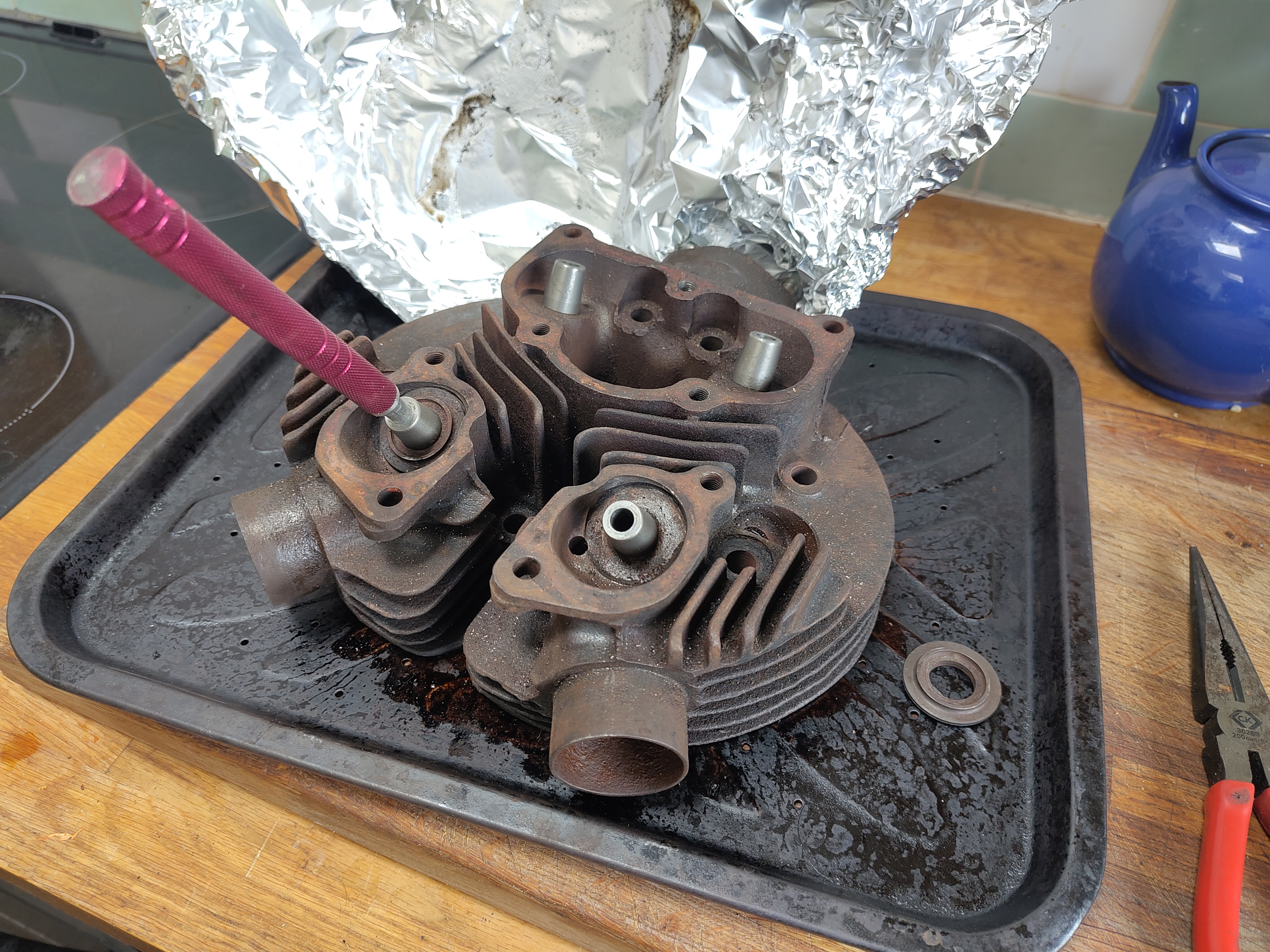
With them all done and the oven hot after a chicken and chips dinner I decided to put them in one afternoon. The valve guides spent half an hour in the freezer whilst the head spent half an hour in the oven set to maximum. In the event the infrared thermometer showed a temperature of 248° C and I was happy with that.


The guides went in relatively easily with help from a small hammer and a drift made from aluminium and bought from Feked; this was ok but I thought a little soft and probably not worth the money. I should have made one from steel.

I discovered during the process that the spring seats did actually fit around the guides and not under them. I wish I had realised that (or at least checked) before I started the work.


The valve seats were badly pocketed as you can see in the picture below. There was really no choice but to recut these and I deliberated for a while over whether to do it myself or to subcontract work to someone else. In the end I don't know why I bothered contemplating it really because it always comes down to the same thing - I'll have a go myself.


Cutting seats in a cast iron head is not reputed to be particularly difficult and indeed these relatively cheap eBay cutters did the job. They did however leave some chatter marks which I was able to refine I gently re-cutting again and again and eventually I got myself to a point where I used the grinding paste technique to remove the last marks.


After a bit of grinding with coarse and fine pastes this doesn't look too bad.


However if you look closely in both of these pictures you can see that the marks are not completely gone and not wishing to remove the head again anytime soon or worse to burn my new valves I resolved to do something better.


I made this cone on the lathe complete with a half inch UNF thread in the middle to fit the same mandrel that the valve seat cutters came with. When I had mostly finished the cone on the lathe I put the mandrel with the cone fitted in the chuck and made my finishing cut on the cone to ensure that the cone was concentric with the mandrel and hence concentric with the valve guide.


That bit of cardboard in the foreground is the template with which you can cut the correct section out of the sheet of wet and dry paper. The system worked well and I was now able to fit the valves.

There's some cleaning up left to do on those gasket faces where I've overpainted a little but essentially the head is ready for fitting.

Saturday, 24 August 2024

FH - rocker box refurbishment

With the cylinder head coming on, it’s time to take a look at the rocker box. We won’t be doing too much, as a number of folk have told me how a BSA A10 rocker box fits straight on and is a much better design - but I don’t have one of those.

We’ll start by stripping out the rocker shafts and cleaning the box.

While the lathe is in action, we’ll replace the 5/16" BSW stud that wasn’t holding the cover on - the covers are held on with a special 1/4" CEI sleeve nut. What we need is a stepped stud, like the original in the inlet side but with a 5/16" BSW thread to go in the aluminium casting. Somebody has already recut the thread in the casting to suit the replacement stud.

We'll start with a bit of 5/16" mild steel round bar. Because it's 1/4" in diameter for most of its length we'll need to be careful when we turn it. What we will do is use the travelling steady on the lathe to support the slender quarter inch section as we turn it to size.


 This turns out pretty well especially when we make a finishing cut with a round nose tool. Cutting the 5/16 BSW thread, I've set the die to its largest diameter such that the thread is a little oversize.


This is where the oversized thread pays off - when it's fitted in the box the the stud fits quite tightly and hopefully won't back out.

The next step is to get the box in the cleaning tank for degreasing; we'll then examine it for damage and polish the outside.