Showing posts with label rim. Show all posts

Sunday, 16 March 2025

FH - front wheel

 A very short blog post just to record that I've finished building the front wheel. 

Of course the first step is to finish the polishing. Here it is with the 80 and 150 grits done:


I needed a break of a couple of hours to let my arms and shoulders recover from the strain of polishing - these hubs are quite heavy. Here it is fully finished:


With a bit of experience, you can build these up wheels very quickly. All the spokes are tight in this view but it's not quite true; I'll leave that for tomorrow.


Saturday, 15 March 2025

FH - wheel building

 With the hubs polished and the proper spokes delivered, we can start on the delightful job of lacing the wheels. 

These will use butted spokes like the originals fitted by Ariel back in the 1950s. The nipple end of the spoke is thinner than the head end - in this case the nipple end is 10 gauge and the head end, with perhaps 1" of spoke length is larger at 8 gauge. The idea is that the stressed part of the spoke is strong without making the wheel ridiculously heavy; this will have the effect of making the steering lighter by reducing the gyroscopic force on the wheel.


I'm building the wheels on a post which is of a suitable size to go through the wheel bearings. The bore of the bearings is 1"; the post I'm using is 1 1/8" so that the hub is happily suspended in mid-air. 

It's essential to get all of the spokes into their holes in the hub before you attempt to fit any of them through the holes in the rim. There is absolutely no chance of getting the spokes in the right place if you attempt to put some of them through the rim before they are all fitted in the hub, so be warned.

For this Ariel/BSA wheel Devon supply the rims in two packets - one for the inner and one for the outer spokes, that is the spokes whose heads are on the outside of the spoke flange but whose length is on the inside, and the converse for the outer spoke.

When polishing the hub I had used a brass brush in the Dremel to clean out the spoke holes. It was easy therefore to slip the spokes into place starting with the outer spokes. Because these hang down, it's a bit easier to do these first followed by the inner spokes.


You can see the butted spoke in this close-up:


Once you've got them all in you'll have this forest of stainless steel wire:


The next job is to offer up the rim. You have to decide which way the spokes are going to point -there is often a fret mark on the outer spoke flange which will show you how the originals fitted. I start with the outer spokes on the upper flange and follow the pattern shown in the spoke flange by the original spokes and fit three or four of the new spokes into their holes with their nipples screwed on by literally a couple of threads. These three or four spokes should all point in the same direction; then I will fit another one in the opposite direction still in the same flange which will serve to stabilize the rim. You can then carry on fitting the same spokes in the same flange until you have all the outer spokes fitted in the top flange. By this point you will have learned that for each outer spoke pointing in the same direction there are three holes in the rim until the next spoke of the same orientation.


When you've done that you can fit all the inner spokes from the top flange as well. This will enable you to ensure that all of the spokes cross in the proper orientation. Don't mix up the crossing, or you will end up with bent spokes.


You can then repeat the performance for the lower spoke flange but this time start with the inner spokes followed by the outer spokes, again to preserve the proper crossing.


Once you've got all the spokes in, you can do up the nipples gradually and evenly until the end of the spoke appears in the slot on the outside of the nipple, like this:


Now it's time to put your wheel in your truing jig or perhaps back in the bike. There's no substitute for using the bike frame as a jig to allow you to adjust the spokes so that the centre line of the wheel is aligned with the centre of the frame. This works beautifully on the Ariel swinging arm frame, but is much more difficult on the Square Four frame - because the Square Four frame is asymmetrical at the rear to accommodate the offset engine.


I made this spoke screwdriver years ago and it's very useful for tightening spokes when you can get to the nipple from the space usually occupied by a tyre. It makes it much quicker to tighten the spokes than using a spoke key.


I'm not going to explain the whole alignment process here because there are reams of material about it in this blog post, written when I was building the wheels for the Square Four. I must say though that these Devon rims and spokes pulled together to give a wheel that was virtually true and aligned out of the box.

Very nice indeed.


Now we just have to do it all again at the front!

Thursday, 27 February 2025

FH - stripping the back wheel

 Finally, and it seems to have been a long time coming, it's time to start on the wheels. I've got the tyres now though I have had to compromise with a 90/90-19 front tyre rather than the 325-19 that I wanted, but at least I have everything.

It doesn't take very long to remove the rear wheel from these bikes despite the fact that I have complicated matters by fitting indicators, and these need to come off before the rear of the mudguard can be unbolted.

The first step is to measure the offset using a straight edge across the bearing housing. With that in place we can measure 7/8" to the edge of the rim.


These are quite common wheels so finding someone that could help with the lacing pattern of the spokes wouldn't be difficult. Nevertheless it is good practice to photograph your wheels before dismantling such that the peculiarities of the spoke pattern can be recorded for the rebuild to come. These Ariel full width hub wheels are simple in that the spokes are of two types - those that fit from the outside, and those that fit from the inside; this results in similar lengths but different head angles for the two types. For the half width hubs fitted to all my other Ariels, there are four types of spokes in each wheel.


When you have all the components delivered, and you have recorded your spoke pattern and your offset you can dismantle the wheel. I've done this a few times now and have discovered the quickest and easiest methods to my mind.

Let it be known that we are not going to reuse any of these components other than the hub. Therefore the best way to remove the rim is to cut through all of the spokes on both sides; I use a bolt cutter for this job which makes short work of snipping through each of the spokes.


There we go. The tyre has not even been deflated yet!


Here is the hub with the remains of the spokes. It's sensible to cut the spokes as near to the hub as possible because it is much more difficult to remove the full length of the spoke from the hole in the hub.


You will find most of those little bits of spoke are stuck in their holes through corrosion and dirt. Just wiggle them a bit to release the gunge, and thread them back through their holes.

Removal of the rim and tyre is equally brutal. All I have done here is to take a hacksaw to the tyre, lubricated with some WD40 and sawn through both the tire and part of the rim such that I can cut through both beads and the tyre will just fall off.

And that's it. Apart from a trip to the dump with this scrap metal and rubber the next job is to start polishing the hub.

Saturday, 3 February 2018

Headlamp Rims & Glasses

As part of the winter lighting upgrade I had to change the original, rusty BPF reflector to a H4 fit reflector to suit the new bulb; I bought this from Paul Goff and all was well, until I came to fit the rim to the shell and found a very tight fit - much worse than normal.

Pushing too hard, I cracked the new glass: £35 down the drain.


However, after the event I realised that I wasn't too happy with losing the old Lucas BPF glass, with the Lucas logo in the middle and that actually this was a blessing in disguise, though it might not enhance my beam pattern too well. I decided to replace the broken glass with the old one, that I would extract from the original rusty reflector.

I started with the spun edge of the reflector here:


And I introduced it to the bench grinder, removing the metal until I broke through the fold:


The spun edge of the rim could then be prised off and the old glass released. You can see the poor condition of the silvering:


The glass was in need of a clean, but otherwise came through the process unscathed:


The new reflector had the rest of the broken glass removed, by pushing the glass out with a metal bar through the bulb hole and by removing the edges with pliers. The glass is held in with a relatively soft mastic which you can cut easily, and if you are trying to remove a modern glass and keep it whole you can cut the mastic around the glass, and then lift the edge of the reflector off the glass at a small slot in the reflector (seen on the far side of the picture). You can get a small screwdriver in here and start the removal process:


I used a similar product to put the new glass back in:


Getting the rim on was still a challenge. I removed most of the new paint from the edge of the shell; made sure both the rim and shell were circular; fitted the rim without the lamp unit and checked clearances for the W clips around the rim.

It was not until someone suggested greasing the shell (thanks Les!) that it went on - a bit of silicone grease on the rim had it slipping on easily.


Friday, 16 August 2013

Wheels again...

Work on the engine has stalled for a moment whilst we wait for FW Thornton to see if they can help out with a ring problem. The bench is now clear, so we can start on one of those other 'waiting in the wings' jobs that we use to fill in when the main workface stops for some reason. Bike building is like that - there is always something else you can do to fill in when waiting for parts.

And so to building the wheels. The 'jig' I use is just a piece of 19 mm ply that used to be part of a desk. The cutaway sections make it really easy to get to the nipples. It has a hole on the middle for the wheel spindle, which is a piece of 1/2" round bar. Using the spindle as a centre, I mark the outer diameter of the rim on the board. Using the offset measurements I made from the wheel earlier (before I stripped it) I make up four wooden blocks to lift the rim off the board to the correct offset. The brake drum, which I use as the datum, is placed face down on the board.
And that is it. There is a much more sophisticated version of this idea in Frank Farrington's excellent book 'The Vintage Motorcyclists Workshop' which includes blocks to control the concentricity of rim & hub - I don't go this far, since when rebuilding a wheel from an intact but rusty version I can buy spokes to exactly the right length and I find that I get very good concentricity by virtue of that spoke length.
So here we go. Set the hub up on the jig:


Add the blocks to establish the rim at the correct offset:


Start adding spokes according to your lacing pattern. You did photograph these wheels before you cut them apart didn't you? It helps if you lift the hub above the jig at this stage, so that you can insert the spokes from both sides. As you add the spokes, try to lay them out according to the lacing pattern. Start with half of the spokes on the lower flange, placing them in alternate holes, pointing in the anticlockwise direction (in the Ariel's case, these spokes have the nipples on the outside of the hub). Then, add the other spokes on the lower flange, pointing them clockwise and crossing the anticlockwise spokes according to the lacing pattern (in Amelia's case, these spokes are threaded from the inside out, have the heads on the inside of the hub, and cross under the anticlockwise spokes).


Then you move on to the spokes in the upper flange, again starting with the anticlockwise spokes. When you have finished, you will have this nice little nest of wire:


Next, lower the hub back on to the jig and lay the rim over the top. Look carefully at your reference photographs, paying close attention to the location of the holes in the dimples in the rim, and make sure you get the rim the right way up. You can easily assemble the whole wheel with the rim upside down, and not notice until you are snugging down the last of the nipples. I know - I have done it!


Now, again we must be careful and work to a pattern, but a slightly different pattern this time. We don't want to scratch that shiny new paint! Starting again with the spokes in the lower flange, and your handy lacing pattern, locate the dimple nearest the valve hole that corresponds with an anticlockwise spoke on the lower flange. Insert one of those spokes in that hole and screw a nipple on a couple of turns. Then, moving clockwise round the rim, insert all the anticlockwise spokes in the lower flange. Then, start on the anticlockwise spokes on the upper flange and continue until you have a nipple on all the upper & lower anticlockwise spokes.
The reason for doing it this way is twofold:
  1. Working on spokes that point in the same direction means that the wheel is very flexible, and you can rotate the rim to get the spokes in the holes without endangering the paint.
  2. Working on the upper and lower spokes in the same direction means that you cannot 'trap' the unfitted clockwise spokes whilst you fit the anticlockwise spokes. Because the clockwise spoke crossings are inside the anticlockwise spokes, they can't get stuck behind spokes that are already fitted.
Keep the nipples really loose to maintain flexibility - you are only trying to establish the lacing pattern and get the spokes in the right holes at the moment.
Next, fit the spokes pointing clockwise. Start at the from the valve hole, and fit the first spoke from the lower flange, followed by the first spoke from the upper flange. Moving clockwise around the rim, fit the spokes in turn - lower, upper, lower, upper - until you have all the nipples fitted.
Now, take the wheel off the jig and have a good look at it. Give it a shake. Make sure all those spokes are entering those holes easily - there should be no tension anywhere at this point. If you are happy, put the wheel on the jig and wind the nipples in until there are 3 threads showing, and repeat the look/shake process. You will probably need to use a screwdriver now, as the wheel will stiffen up.


Now, with the wheel back on the jig, wind the nipples in until there is no thread showing. As you do, make sure the spoke heads are seating properly in their countersinks. Look & shake again. Next step, run all the nipples down until the end of the spoke is level with the bottom of the screwdriver slot in the nipple; then go around again until the end of each spoke is level with the very end of the nipple - you will need a spanner or a spoke key this time. Off the jig again, you should find you have a very stiff wheel. If one or two of the spokes are still loose, snug them down now, as evenly as possible.
This gentle step by step approach to spoke fitting ensures that the wheel comes off the jig needing very little trueing up.

So next, trueing up.

Hopefully, having built the wheels on the jig, we will have very little truing to do. However, there is usually some runout, but the offset is probably good. By the way, the offset I measure from Amelia's original wheels was:
  • Rear 9/16" on the brake side
  • Front 1 1/4" on the brake side
Now, what is runout? There are two types of runout - lateral runout and radial runout, as illustrated by this handy picture I made:
Radial run out is, pretty obviously, an eccentricity of the rim relative to the hub. Lateral runout is when the axis of the rim is not parallel to the axis of the hub. Easier to explain with the pictures!

So, how to fix it? Well, you can do miracles with a spoke key, but first you have to figure out what is wrong. To establish this, you need to set the wheels up in a jig, like this:


This is made from two pieces of timber, glued and screwed to a cross member, held in the vice. There is a V-notch in each piece for the wheel spindle to rest in. At the bottom, adjacent to the rim, are two pins:

One is set up so it almost touches the side of the rim; the other so it almost touches the outermost edge of the rim. Spin the wheel in the jig, and you will be probably be able to see both lateral and radial runout. Move the wheel slowly, and you will be able to quantify the run out in both directions - it is essential to mark the rim where the runout is worst.

You'll want to get the runout down to 1 mm, or 1/32", in both radial & lateral directions. You've probably got about 3 mm or 1/8" now, right?

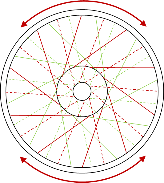
So the key to tackling runout is the proper adjustment of the spokes. Here's another of Simes' handy diagrams:

Ain't that pretty! A few words about it:
  • The dotted lines show the spokes on the non-brake side
  • The solid lines show spokes on the brake side
  • The 'upper half' and 'lower half' relate to positions on the wheel relative to a mark you will make on the rim during the truing process
  • The green spokes go ant-clockwise
  • The red spokes go clockwise
Tackle the radial runout first. Roll the wheel in the jig again, and  relative to your pointer, mark the rim where it has most runout, i.e. where it is lowest against the pointer, where the distance from the outside of the rim to the centre of the axle is greatest.

Roll the rim until that marked point is at the bottom, and now you will have  spokes in the lower half and spokes in the upper half. Because we have the worst runout at the bottom, the spokes in the lower half need to be shorter, and the spokes in the upper half need to be longer, to reduce the runout and make the rim concentric with the hub.

So, you must appreciate that the spokes which are more or less horizontal, and radiate from the extreme left and right of the hub don't have any effect on the runout. Conversely, those running vertically are controlling the runout and it is these that will be adjusted most. Those that run diagonally from the hub have more or less effect depending upon how vertical or horizontal they are.

So, using this diagram:


We can see that the spokes within the red arrows have more effect on the runout than those that are outside the arrows. To correct the runout, hold the wheel in the same position (with your mark at the bottom) and loosen the spokes within the red arrow at the top by, say, 1/4 turn. Loosen ALL the spokes within the arrow - the red, green, dotted and solid ones. Then tighten the ones at the bottom, within the arrow, by the same amounts.
When you have finished, measure the runout again. It should have reduced a little. Now  repeat the process until you are satisfied that you have minimised the runout.
Correcting lateral runout is a little more complicated. Remember:
So again, locate the point where the runout is worst, and mark it. In this case, 'worst' means the point where the BOTTOM of the rim is furthest to the RIGHT, like the diagram above.

To tackle this lateral runout, adjust the spokes in this sequence:
  1. Loosen the SOLID spokes in the lower half of the wheel by 1/4 turn
  2. Loosen the DOTTED spokes in the upper half of the wheel by 1/4 turn
  3. Tighten the DOTTED spokes in the lower half of the wheel by 1/4 turn
  4. Tighten the SOLID spokes in the upper half of the wheel by 1/4 turn
Here is the diagram again to remind you:


When you have finished, measure the runout again. It should have reduced a little. Now  repeat the process until you are satisfied that you have minimised the runout.

And that, ladies and gentlemen, is that. All that remains is to file off the protruding spoke heads:


File them flush with the nipple, so there is no danger of them popping a neat hole in your inner tube. Fit a nice new rim tape, put the tyre on and go and have a beer in the garden.

Saturday, 20 July 2013

Phase 2 - and wheels...

Regular readers will know that I didn't plan to start any finishing work until I had completed mechanical assembly, such that I could give myself some time for research and so that I wouldn't end up drilling holes or cutting & welding components that were already painted. This is a great philosophy when you are making modifications or when the bike is so incomplete that you are forced to buy parts from more or less reliable sources.
 
A case in point is my indicator brackets:
These have moved all over the place on the 'L' stays in an attempt to get them in the right place.

However, a mechanical build followed by a final build after painting doesn't work with the wheel rims and their gold lined Damask Red centres. I didn't want to have to break these down again for painting, since I will be trimming the spokes to fit. Wheel building is also time consuming and the wheels probably won't be modified at all.
 
I collected the rims from JD Wyatt in Thetford a few days ago, so I am all ready for wheel building now. When discussing the wheel plating with Tony at JD Wyatt, he advised that with a painted centre it would be wise to avoid polishing the painted area and leave it in the as-blasted finish, so that is what we did:
 
 
So, now we need a painter. Of course, I want to have the wheel rim centres matching the tank, so I'll have to get that done at the same time. This is starting to look expensive...
 
Aerographics of Horsford, near Norwich are a long established company set up by John Spurgeon back in the '80's specialising in custom paintwork for trucks, cars, bikes, scooters - you name it, they have done it. They are set up in old farm buildings in an area once renowned for apple farming, and have some great work shown in their website.
 
I spent an hour or so with John learning about his company. John has a wealth of experience and has painted several Ariel tanks before. We looked at many images of Ariel tanks while discussing the location of the lines. This is quite involved, since Ariel hand lined their tanks (so no two are necessarily identical) and many restorers have 'done their own thing' over the years. Additionally, some of the source material shows dimensions for the lines that would leave them visually too close to the badges or the knee grips.
 
So, I took the whole tank to John with badges and the knee grips intact and we laid out the lines in masking tape:

 
So there it is. John says he will turn this and the rims around in 10 days, so watch this space...


Monday, 15 April 2013

Wheels


Sample spokes
Amid engine machining and gearbox rebuilds, I decided it would be good to actually ride Amelia at some stage. Standing in the way of this was a set of very rusty spokes on both wheels. I'd hoped to get away with commissioning the bike on it's own wheels, without any form of rebuild (continuing my 'Phase 1' rebuild with no chroming or painting) but it was not to be. Both wheels had at least one broken spoke, and the remaining spokes were very thin in places.
So, a rebuild it had to be.

Amelia has half-width cast iron hubs, front and rear. The front is the 'Qualcast' half width hub fitted to all telescopic-fork Ariels prior to the appearance of the full-width alloy hub in 1956, and the rear is the 5-stud QD hub. Tyres are 3.25-19 front on a WM2 rim & 4.00-18 rear on a WM3 rim.

Max has found some tyres
So, gathering parts. I used Central Wheel Services for spokes & tyres, since they give outstanding service and their prices for tyres were very good. I bought traditional Avon Speedmaster & SM MkII tyres, still made today in a modern soft compound.

Close inspection of the spokes revealed plain spokes on both sides of the wheel at the front, with butted spokes on the drive side at the rear, plain on the other side. This matches the description in the parts book perfectly. However, it didn't match the records at Central Wheel, so I had to provide sample spokes for them to manufacture against. I chose stainless spokes and plated brass nipples this time, since I was not at all happy with the nickel plated steel nipples I bought for the Bantam which, 2 years on, are rusty.

The first thing you must do when rebuilding a wheel is to remove the old tyre. Don't think about using an old tyre for a second - even if it has tread and sound sidewalls, the rubber will be hard as nails and will have you sliding down the road. 

Interesting paint under the original rim tape
Removing tough old tyres can be a challenge, and I often dispense with the traditional levers in favour of a set of bolt cutters, which I use to cut the wires in the bead. On an older tyre, I'll cut the rubber with a Stanley knife to ease the passage of the bolt cutter. Don't bother trying this technique with a modern tyre though, there's wire everywhere!
Rear rim offset
Next, find yourself a nice stiff flat board. A piece of 3/4" ply would be good. We need to measure and record the offset of the rim to some datum on the original wheel - the brake drum is very convenient. Place the brake drum face down on the board, and measure the distance from the edge of the rim to the board

Amelia's front wheel offset is 1 1/4" to the rim on the brake side;

On the rear, it is 9/16" to the rim on the brake side. On the rear, the offset is measured with the brake drum removed.

The next step is to photograph the spoke patterns. Make sure you have pictures of which spokes overlay others, which holes the go into on the rim and please also look at the dimpling on the rim holes and makes sure you know which way round the rim goes. 

Those of you who have read my Bantam pages will know I have rebuilt at least one wheel with the rim the wrong way round - the result is not pretty as all the spokes will be bent.

My reference photos are shown further down the page.

The next step is a real turning point in the rebuild: take your best bolt cutter, and cut the all the spokes. Do it within an inch or two of the hub. If you cut near the rim, it will be much more laborious to feed all the rusty spokes through the dirt encrusted holes on the hub.

Bolt cutters - did I really do that?
The next step is to get the rims off to the platers. This takes a while, so don't hang about! While they are gone you can clean up the hubs, get them painted, recondition the brake plates and replace the bearings.

Incidentally, I spoke to Tony at JD Wyatt Contract Polishing, who told me that it would reduce the cost of the polishing if I were to leave the painted rim centres in the blasted condition. Since this would provide a key for the paint, this is what I decided to do.

Spoke Patterns

Spoke patterns for the rear wheel:


Spoke patterns for the front wheel: