Showing posts with label connecting rod. Show all posts

Friday, 17 November 2023

FH - Plastiguage and the big ends

 Next step is to check the big end clearances. I've measured the journals, but I wanted to get some evidence of the clearance that I had ended up with after fitting new -0.030" shells. There isn't much detail on what the acceptable clearance is  before you must regrind, other than the data describing the sizes you regrind to and the recommendation that there should be minimal clearance after regrinding.

Waller indicates 0.003"- 0.004" for the big end shells used on 1948-1955 Square Fours (Fifth edition page 37); Phil Irving quotes 0.001-0.0015" clearance per inch of diameter (Tuning for Speed 3rd Edition), which equates to 0.00165 - 0.0025" for my 1.65" big end. Mr. Irving, otherwise known as 'Slide Rule' using those delightful pseudonyms beloved of motoring writers in the '40's, also notes that the clearance can be much larger as long as oil pressure is maintained.

So, let's introduce Plastiguage. This is a paste, extruded into rods a bit like Plasticene. You trap a bit in the bearing and squash it, so that the known Plastiguage rod diameter is squashed to take up the clearance of the bearing - you then use the card provided to determine the clearance from the width of the squashed Plastiguage. Plastiguage comes in different sizes to measure different clearance ranges.


So, you cut a length to suite the bearing like this, and then you make up the bearing. You make sure the bearing is clean first.


When you open the bearing again you can see the squashed Plastiguage and you can compare it to the card. This suggests something like 0.002 - 0.0025" clearance for the drive side. I'm happy with that.


This is the timing side, and it's about the same:


All good there then. Next job is to make sure the oil flows into the big ends. I'll inject it into the timing side oilway:


And it comes out the drive side big end!

During this process, I removed (with a little heat) one of the gudgeon pins from the new IMD 7.25:1 pistons I got from the AOMCC so I could check the fit in the connecting rod little end bearings. This proved to be perfect once I had cleared a small burr from one side of both bearings; not sure how that came to be there.

Happy days.

Tuesday, 14 November 2023

FH - Crankshaft assembly

 Now we need to look at the crankshaft.

First up is the sludge trap. Keen readers will know that we cleaned this out some while ago, so all I have to do today is run a cloth through the hole to clear any dust and debris:


The sludge trap was cleaned at the same time, so we just give that a rub over with a cloth.


One of the flywheel bolts passes into the sludge trap - perhaps to stop it rotating. It's safely in place:


I'm using the hexagon type sludge trap plugs. This one locates the drive end of the sludge trap:


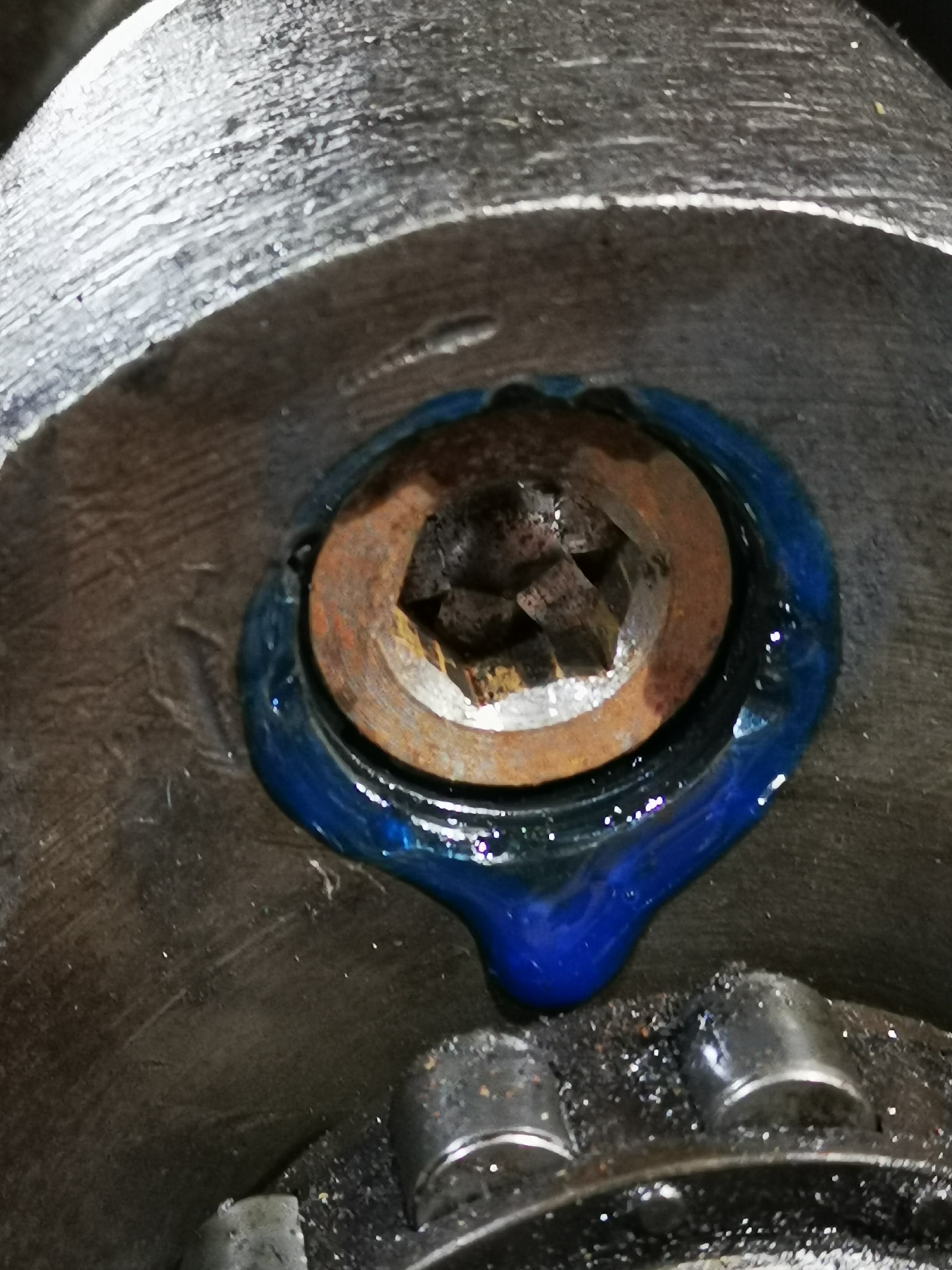
It's held in place with medium Loctite threadlock:


This is a terrible picture, but it serves to show the plug has successfully located the end of the sludge trap:


The plain timing side plug is also held in with Loctite medium threadlock.


Next, with the sludge trap closed up and the flywheel bolts done up tight, we can trial fit the connecting rods using ordinary nuts. We don't want to use the real nuts yet, since they cannot be reused.

Now, these big ends should be 1.657/1.6565" according to the BSA data sheet; this one measures 1.656/1.655", so we are 0.0005/0.002" undersize. I felt this was close enough and ordered the corresponding -0.030" shells from the twin spares man at the AOMCC.

The first trial assembly is now complete, and you can feel a small amount of play with dry big ends; this disappears when the bearings are oiled.

I've ordered some Plastiguage to determine what the clearance really is. 

More on this later.

Wednesday, 18 October 2023

FH - no progress except for COVID

 Well, there's not much happening at the moment. After a few fun packed days babysitting the grandchildren, I have finally caught COVID - fortunately in it's latest rather benign variant.


In other news, the missing big end bolts have arrived from Draganfly. 


With some detailed advice on some crankcase questions, I'll start building the engine when I'm back on my feet. 

Sunday, 4 October 2020

W/NG - Barrel & Piston

The piston that came out of the W/NG surprised a few people. It looked like it had been wire wound at some point in it's life. It was flat-topped and had an oil control ring, both features that differ from standard.


Here's a new +0.040" Ariel piston - new old stock, still in it's original wrapping, from AOMCC singles spares. You'll see it has a raised crown and three compression rings.


The old piston was not in a happy place when it came out. The top ring was in at least three pieces - at least, I found three pieces. Not enough to make a whole ring...


The small end was also in a pretty bad way and in fact the rod eye turned out to be oval. The bush had no oil slot cut in it either.


I had the barrel rebored and honed to suit the new piston by L.A. Whitmore of Briston, Norfolk - an excellent little company which unfortunately is no more. The rebore took out most of the wear.


Much later, after I had finished the bottom end I cleaned up the barrel using my bench-mounted and my flexible wire wheels. There is actually a fin repair here as well - that must have been done in Italy.


I followed this with two coats of engine enamel from Paints R Us which appears to be excellent. We'll see when it has been in service for a bit.


For my next trick, ladies and gentlemen, I will replace the barrel studs after cleaning them on the wheel. I've put them in with Loctite 243 medium strength thread locker.


I need to check the rings. They are all showing a 0.012" gap - rather large, but well with Ariel's 0.030" limit and they are very difficult to measure as they are cut at an oblique angle and consequently any sideways movement opens the gap.


Next, I'll check the fit of the gudgeon pin in the small end. It slides in easily with no rattle; as I would hope. Alpha Bearings reamed this to Ariel specification and made a bush to suit the small end eye.


Five minutes with the Rothenburger has the piston warm enough to receive the pin and a few seconds later it is on. Next job is to fit the circlip - but cover the crankcase mouth before you try. The circlip is bound to ping off somewhere and the last place you want it is in the crankcase.


Don't try this delicate operation without gloves if the piston is still warm, and make 100% sure the circlip is seated correctly:


I don't have a piston ring compressor - I maybe should have bought one but ever since building BMC A series engines when I was much, much younger I have used this approach - a strip of tin and a ty-wrap. Works a treat if you get the tension on the ty-wrap just right for the barrel to push the tin down and off the rings, and it's dead cheap for when you need four of them.


See? all fitted with no drama, though since writing this I remembered I had intended to fit the engine plate covers before the barrel went on - access is a bit more restricted now.


That's Morris SAE50 in the bore. Next job is to time the ignition, finish fitting the magdyno and the chain cover and start preparing the cylinder head.


Thursday, 22 November 2018

Gudgeon Pin Extractor

Gudgeon or wrist pins retain the piston to the connecting rod with varying degrees of clearance, transition or interference fit according to the predicted running temperature of the engine, and are retained by a circlip at each end in addition to any fit. This means that removal of the circlips will sometimes allow the pin to slide out, but more often than not you'll need to warm the piston such that it will release its grip on the pin. Obviously, belting the end of a tight pin will do your connecting rods no favours at all, so anything other than light tapping is a no-no.

A much better approach is to use a gudgeon pin extractor. These usually consist of a threaded rod passing through the pin, some means of holding the pin, a tube large enough to allow the pin to come out and a large washer to spread the load.

I made this extractor to deal with the FH gudgeon pins, which were quite tight. It is made of a bit of 1" tube, with a closed end turned from aluminium; that's M6 threaded rod in the middle. The tube is long enough to accommodate a 3" gudgeon pin.


A turned steel plug fits neatly into the gudgeon pin aperture in the piston and is reduced to just fit inside the pin such that it doesn't slop about. It's threaded M6 internally and is retained with a nut for the moment.


Here it is, set up and ready to extract the first pin:


Here's the extractor set up on the piston. The end of the tube is shaped to fit the piston, spreading the load over the piston wall:


A blast of heat on the piston crown and some steady winding are all that is necessary to draw the pin out of the piston, without placing any side load on the connecting rod. When you have done winding, the pin is neatly enclosed in the extractor:


Job done.

Friday, 26 July 2013

Preparing the Crankcases


This, as all you classic motorcycle fans will know, is a sump plate. It is extremely nasty - it is pitted, bent, and is about as flat as the surface of the moon.

I'm afraid it has to go in the bin, to be replaced by one of Drag's excellent new ones complete with drain plug and magnet. Theirs are flat, thicker and made of nice strong modern aluminium!
 
Here it is in place, trial fitted with the pick up pipe and the suction strainer. To the right of the timing side main bearing, you can see the riveted cover over the drain from the oil pressure relief valve.

 
You can also see in that picture that the oil pick up pipe bolt has been wire locked into place.
 
And unfortunately, that is where the picture record ends. My camera packed up, and now I have no record of actually assembling the cranks into the cases...
 

Until we get to here, which is just to record that I did close up those tab washers correctly! That's plumbers pipe cladding protecting the rods, by the way.


Tuesday, 18 June 2013

Bottom End Assembly

Thanks to the ever-helpful Brenton Roy, I have the torque figures for the connecting rods:


This is from the excellent AOMCC Knowledgebase.

Saturday, 15 June 2013

Just to assimilate thoughts on the bottom end...

An empty but patient crankcase
Not a very exciting blog post, but it will help me to figure out where I am on the engine rebuild...

So, the state of play this morning:
  1. The cases are fully machined, clean and partially polished.
  2. The connecting rods have new bushes and shells and have been polished. New nuts are available.
  3. The crankshafts are machined and cleaned, and I have the new oil way plugs available
  4. The camshaft has been machined & cleaned
  5. I have the coupling gear cover polished, the coupling gears and their seals & bearings ready and I have a new gasket and a set of studs and nuts from Acme Stainless. I also have a coupling gear 'pusher' to help me pull the crankshafts through the coupling gears.
Front crankshaft during stripdown
So I need to do these things next:
  1. Finish polishing the cases
  2. Assemble the crankshafts & connecting rods
  3. Assemble the crankshafts & camshaft into the cases
  4. Fit the bottom end into the bike
  5. Assemble the coupling gears and fit the cover - filling it with oil through the overflow hole
And I need to make these decisions:
  1. Decide what building lubricant to use
  2. Decide how to torque up the big end nuts
  3. Decide what sealant I am going to use on the crankcases
  4. Decide what oil I am going to use
I'm sure there is more...

Wednesday, 12 June 2013

Starting on the engine!

Well, summer's here and the bike is coming together. I've finished my welding work, the wheels are still away, and most importantly I have some time away from work to get to grips with things at home.

So, in a break from repainting the kitchen we will start work on the bottom end.
 
I'm dithering around polishing the crankcases which is a noisy & messy job & which stops me rebuilding the engine. Someone also suggested that polish would hinder cooling - but equally it is obvious that the engine was once polished - it is deeply tarnished now, but you can see it is still very smooth - you can also where it wasn't polished!


But, I have all the parts and can get moving with the rods & cranks.
 
You'll recall from previous posts that the rods have been cleaned and polished and have spent the winter protected by some pipe insulation in their own box. I have small end bushes and big end shells from Drags along with new big end nuts, also from Drags.
 
These are shown in the adjacent picture and will have to be pressed into place and reamed to the finished size.

 
The sizes are shown in the table below and are around 11/16" - but will have to be sized to fit the factory specification using a suitable adjustable reamer. In this case we will use a 21/32" - 23/32" reamer, which are readily available but are of highly variable quality. Beg, steal or borrow a decent one if you can! If you must buy an internet cheapie, take a look at a few things before you use it and if it is no good, send it back!

Take the reamer to pieces. Measure the length of each blade, and make sure they are equal.
  1. Look at the retaining nuts, make sure they are not too loose and clean the threads
  2. Clean out the grooves in the reamer body and make sure the blades can sit snuggly down in the grooves. You don't want any swarf in there.
  3. Put the reamer back together, and measure the diameter across two opposite cutting edges (this only works on six blade reamers) at each end of the blade. The dimensions should be the same! They are not supposed to be tapered. Repeat the operation for the two other pairs of blades.
So, to fit the bushes. You can use a press for this, if you have access to one, but a bench vice comes a close second. You could also use the draw-bolt method, but I suggest the loads are probably too high for that approach. These bushes are quite tight.

  1. Find a socket or a piece of tube which is small enough to support the small end eye, but large enough, both in length and internal diameter, to receive the old bush.
  2. Open the vice enough to receive the rod, the socket and the new bush plus a couple of millimeters.
  3. Find a piece of soft sheet (brass for example) to protect the end of the new bush.
  4. Align the socket, the rod eye and the bush. You might benefit by putting a short rod of about 1/2" OD inside the assembly, just until you have the new bush a couple of millimeters into the rod, just to keep things lined up.
  5. Nip the whole lot up in the vice with your protective sheet on the jaw pressing on the new bush.
  6. Operate the vice to push in the new bush, pushing the old one out into the socket. You will probably find the initial force required is much higher - and you might get a bit of a bang as the bush starts to move. This is normal. Don't be afraid to apply a bit of heat to the small end eye to get it moving - but go easy, this is aluminium. No Oxy-acetylene here!
  7. Carry on pushing until the new bush is more or less flush with the face of the rod. My bushes are about 0.5 mm over length at the moment.

The next job is to drill the oil hole. Do this before reaming and you don't need to worry about deburring later. The Square Four has 3/16" holes in the small end eye.

Next - reaming to size. Get ready with your gudgeon pin, your internal micrometer or bore gauge & a 1" micrometer.
 
Now, adjustable reamers are really scraping devices. They are designed to scrape out small quantities of metal from holes and as you have seen (from when you inspected your new reamer) they are not as rigid as solid reamers and can only be used to take small cuts.

When you set the reamer up for the first cut, back off the adjustment collars (i.e. screw them away from the square end of the reamer) to reduce the diameter of the reamer until you can put the reamer into the bush. Now adjust it larger until it just begins to touch the inside of the bush. Turn it using a tap wrench a couple of times with some oil.

Be careful to twist the reamer such that it is concentric with the bush; make sure the blades pass right through the bush. That way you will minimise the potential to cut a tapered hole.

You want to increase the size of the hole in very small steps, testing with the gudgeon pin at each stage -  DON'T SKIMP ON THE CHECKING!! Small end bushes are relatively cheap, but replacing them repetitively is tiresome. Increase the size of the cut by turning the collars by 1/8 of a turn each time, and turning the reamer in the hole 3 or 4 times. Always make sure that the top collar is tightened down.


A few more thoughts:
  • NEVER turn the reamer BACKWARDS – can You could break or chip a blade.
  • Never put more than ¼ turn on the collars
  • If the reamer jams, loosen the blades and pull the reamer out and start again. Remember a jam will leave a number of ridges and these have to be cut away or it will happen again.
  • Make certain that the collars are tight.
  • Clean the reamer after each pass.
  • Do not push down on the reamer too hard or it will jam. Take it slow and easy - this is supposed to be a hobby remember? You don't need to hurry, you are enjoying yourself right?
  • On each turn try to stop in a different place.
  • Use oodles of cutting oil.
So, now we have our reconditioned connecting rod:


So, repeat the operation for the other rods and you will end up with a little heap of scrap like this:

So here is a table showing the dimensions I have ended up with:

Small End Bush
Big End
Factory Specification
0.6868”
0.6863”

0.003" wear allowable
1.375” min (journal)
Cylinder 1
0.686”
1.3765”
Cylinder 2
0.6869”
1.3745”
Cylinder 3
0.6863”
1.377”
Cylinder 4
0.686”
1.3775”

I had to order a couple more bushes from Drag's since I wasn't happy with No. 2 & No. 3. The table above shows the new dimensions.

And now, over the last couple of days I have polished the cases. I made sure that I polished only the areas that were polished in the factory all those years ago:

Next stop, bottom end assembly!