One of the nice things that arise from a dedication to one make, one era or perhaps just motorcycles manufactured in one country is a collection of specialist tools. Today, I'm quietly cleaning paint out of the threaded holes in the frame, yokes and swinging arm with CEI taps, while I wait for other bits to arrive and for the rest of the painting to be finished:
The fork stanchions have arrived:
And we have new seal holders, seals and progressive fork springs:
A few spare minutes found me progressing the build a bit further. Last night I ordered the engine parts from Draganfly; the pistons and big end shells have already arrived from the AOMCC Twin Spares chap. They look excellent:
The swinging arm goes in easily and is bolted very loosely. It's held up with an old shock.
I've put the steering damper back in; the pin tapped in easily.
Now, I was careful to ask the painter to avoid grit blasting the oil tank, and he has indeed prepared that by hand. However, the fork sliders would have benefitted from blanking off as they are full of grit; I made this swab to clean them out:
Running paraffin down the slider in the cleaning bath I swabbed the grit out:
There's quite a bit - that was worth doing:
I cleaned the fork legs with 180 grit Scotchbrite - they are not very good:
I ordered a set of seals and new seal holders yesterday. At £115 a pair, it's worth buying a new set of hard-chromed stanchions as well.
A while ago, last May in fact I removed the SilentBloc swinging arm bearings and I wrote about it here. Since then, lots of things have got in the way - not only the Honda stuff, the QR50 and the CX500 but also the rear mudguard and the oil filter for the FH and of course the W/NG engine rebuild. Anyhow, as regular readers will know, the oil filter is done and I am on to the swinging arm. I'm doing this next as I want to check the oil filter will fit (and can be re-fitted) with the FERC in place and I can't do that without the swinging arm fitted, so here goes.
Before I start, the inspiration for this job, the details of the bushes and indeed the spindle (and it's machining) came from Steve Carter, who's done more miles on Huntmasters than probably anyone alive today and who is a stalwart member of the AOMCC and a daily contributor to the AOMCC forum.
Thanks Steve.
So, I have two oil filled bronze bushes measuring 22 mm ID x 32 mm OD x 50 mm long that I bought from Simply Bearings under the part number AM2232-50. The cleaned out journals for the old SilentBloc bushes measure exactly 1 1/4", which is 31.75 mm and we will want an interference fit of maybe 0.002" or 0.05 mm.
Well, you know what is coming next don't you. Charlie will start banging on about the virtues of his mini-lathe. What puzzled me for a while was how to hold the bushes to machine the outside diameters to size - I considered expanding mandrels, grub screws in a mandrel and Loctite. I was nervous of using Loctite as the these bushes are porous and I was worried about getting the bush off the mandrel.
As it happened, I just went for it and did it. This Ever Build cyanoacrylate is old and cold and may not work very well but I put a 1/4" wide ring of it around the 22 mm mandrel and slid the bush on - in a few minutes it was set.
I machined the bushes quickly and easily to size using the power feed and a carbide tipped left hand tool running at about 400 rpm. and it cut beautifully with no complaints from the glue. Actually, the cutting forces probably don't test the glue very much as this bronze is quite soft.
When considering fits, I had thought about cutting a clearance fit and using Loctite 603 Bearing Retainer, but discarded the idea as I should be able to machine a reasonable interference fit and not require a liquid retainer. As it turned out, this worked beautifully with the first bush which had a medium driving fit, but I cut the second one slightly undersize so I used some retainer with that. They both held up to the reaming forces.
The mandrel knocked out very easily and the bushes were pushed in flush with the end of the swinging arm tube, since I knew that there was minimal end float with the swinging arm in the frame:
The spindle material I got from Steve was 7/8", which is about 22.25 mm so we needed to ream the bushes. The spindle needs to carry the original stud through the middle, which created a problem - my lathe is not long enough to drill out a suitable round bar, nor does it have the capacity to pass such a bar through the lathe spindle. This is where Steve comes in again - he had a bit of bar long enough to provide spindles for two of his bikes, mine and another friend’s so he ended up making four. All I had to do was trim it to length to suit my frame, which I could do with a fixed steady.
With the reaming done, I could oil and fit the spindle - fortunately it fitted both sides simultaneously with out any adjustment, so I was lucky - I had taken no precautions to align the bush I was reaming with the other bush.
The fit is great - there is no play that I can feel on the bench, though it may be a different story when the bike is on the ground.
Last thing I need to do is fit a grease nipple, though I want to assemble the arm back in the bike so I can see where to put the nipple for best access.
These plain journal engines run close tolerances and need a decent oil filter. Modern oils keep the dirt in suspension and if there is no filter, the oil becomes contaminated very quickly.
The SQ4 has a Norton commando oil filter, like this one, fitted under the gearbox where:
you can't see it
you can get to it easily
it doesn't ground on kerbs
We'll need a similar site for the filter on the FH.
There's a lot of space behind the engine, between the engine/gearbox plates - but not for this filter, which is marginally too big for this location.
Beneath the swinging arm and in front of the mudguard is a likely location used by many FH owners. I'll need to find a location where I can easily mount the filter and where the oil lines will be able to get to and from it without kinks - and it must also fulfil the other criteria I listed above.
This is probably no good - there is nowhere to mount to and the oil line routing could be a bit tortuous:
This is an example of a mounting used in that area:
This one is on AOMCC forum member Steve Carter's Ariel Cyclone.
And another - this is AOMCC Kieth Mettam's filter:
Another one from Steve Carter, this well used Huntmaster carries a Morgo filter - these are smaller than the Commando filters and easy to place - but they are quite expensive and it makes sense to me to use a unit I already have elements for, commonality of spares and all that:
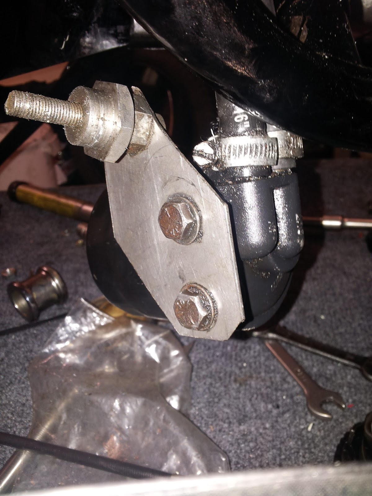
This is my choice. I'm using a mock-up bracket, made from a bit of 20 swg sheet, welded to an old footrest bar sleeve nut and placed in the sidecar lug beneath the swinging arm:
It's too far back, and the oil lines foul the gearbox casing:
Time to cut it up and shift it around:
To become this ugly but effective thing, including a bit of butt welding practice:
Also pictured is the beginning of a special bolt that will locate the filter bracket in the sidecar mount.
This is better. It's further inboard to allow the oil lines to pass the gearbox outer casing, and further forward to guarantee the filter clears the mudguard and rear wheel:
The next step is to replace the bracket with one made from 3-4 mm sheet, and finish the special bolt that holds it in place. I'll use the same old sleeve nut, but I will probably machine a journal in it to fit in the hole properly.
Here's the finished bolt:
It's in the wrong side, but I'm just testing for fit. I wanted to make it look like the swinging arm nuts.
I'm tubing up using a mixture of Huntmaster and BSA A10 oil lines. The long A10 lines stretch from the engine right around under the gearbox to the oil filter:
I've spent a long time faffing around with these connections, even considering moving the filter altogether. In the end, after a session mulling it over one night in the workshop with my son, we concluded we could get it all in there if we modified the fittings:
I've shortened the unions in the lathe and gained about 5/16" which is enough to give the gearbox it's full range of adjustment. This allows the gearbox to move and the oil lines to follow the routes I'd laid out. A minor problem is that the return to the tank is touch on the long side and the route has to cover a 120° bend on top of the gearbox, which is a bit unsightly.
Next, it's time to fit the swinging arm and understand how the FERC fits around it.
At first, I struggled to get it in at all. It's difficult because the frame tubes behind the swinging arm mount are more narrow than the width of the swinging arm...
The secret is to lift the frame at the rear, drop the swinging arm and come at it from underneath, with the swinging arm cocked over so the offside is higher than the nearside. Once you get the nearside more or less adjacent to the nearside mount, the offside will rotate up into place. This works because there is more space in front of the offside swing arm mount - the gearbox interrupts the nearside.
I made a decision about the bushes - Steve Carter, marathon FH rider from the AOMCC changed his rubber bushes for a pair of oilite bushes and a much larger swinging arm spindle, and I am going to replicate that approach. Those bushes have a reputation for being a bit of a pig to remove. I thought I would try a hole saw, between the two metal tubes and sawing only through the rubber. It worked fine, with a bit of silicone grease to prevent burning but ultimately my saw was too short:
I resorted to the more traditional approach - a twist drill:
This works very well and of course if sufficiently long will cut all the way along the length of the bush:
The next job of course is to remove the outer sleeves from those 'SilentBloc' bushes. Easier said than done.
My first thought was to weld a plate across the sleeve and drive the whole lot out. I got a decent weld, and then proceed to drift it out - and tore the weld out with the plate attached. The sleeve stayed in the swinging arm.
The Dremel is a more traditional approach and works a treat. I cut a slot in one with a burr; the burr was ruined, but cut one slot before it passed away.
Once you have the slot cut, you can prise the sleeve out of contact and it will be loose enough to drift out.
Let's have a look at the brake pedal and crank arrangement next. Here's the crank in place - the rod is very rusty & I broke it trying to dismantle it...
The crank is held in place with a hex head screw (which I think is 5/16" CEI) and a large washer - both of which are missing. There's a clevis on the end of the brake cable.
I'd thought I might buy a new rod assembly from Acme, but having attacked the original with the wire wheel I see that much of it (rod aside) is in pretty good shape and would replate, so I have sat the broken bits in the vice with some Plus-Gas in them.
Drilling that broken rod out is going to be straightforward. Here's how I did it:
I decided to use the lathe to ensure that I drilled the broken std out on-centre. Since it was tricky to hold the banjo shaped swivel in the chuck, I made a simple collet out of a bit of aluminium round bar. The larger part of the swivel would sit behind the collet, which grips the parallel part.
I used the collet to hold the swivel in the 3 jaw chuck, and drilled the bit of broken rod out with progressively larger drills. I cleaned up the thread with a tap.
The rest of it cleaned up easily with the wire wheel. The bolt and washer used to retain the bell crank in the frame are missing - I understand (thanks to Mick D on the AOMCC Forum) that the bolt is 5/16" CEI, about 3/8" long. The thread needs cleaning up:
I've turned up a new washer from a bit of 25 mm 303 round bar:
Moving on, the brake pedal is all good and the spindle fits nicely into it's hole in the frame.
No idea why it is plated though. The spring, although it fits and is working, is very pitted and will need replacement:
I've made a new brake rod from a piece of 1/4" round bar. The collet chuck and tailstock die holder are very useful for jobs like this:
Here we go, new and old:
All fitted up. Next step is a new brake pedal spring and then the brake light switch.
Update:
The brake light switch fits onto a welded bracket on the frame down tube, right above the swinging arm, close to the abutment for the brake cable:
The brake cable uses a clevis arrangement to connect to the bell crank. This one is a bit long, and needs a washer and a split pin: