Showing posts with label Smiths. Show all posts

Saturday, 30 March 2019

Speedo Gearbox - W/NG

Since I've had my W/NG, I've been suspicious of the fact that it is (or was) little faster than my Bantam, struggling to reach 50 mph without a wind behind it.

A W/NG with the wind behind it
So, I was interested in a thread on the AOMCC forum on the subject, in which fellow W/NG rider Alan Moore wrote:

"Calculating the required ratio to give 1600 revolutions per mile traveled by the front tyre (with the 43T/14T hub gears) results in a required gearbox ratio of 8:12 (it reduces the input turns by that ratio). So the input pinion has 8 teeth and the output pinion 12. So my 8:14 ratio is a little bit out and gives 1400 revs per mile which means the speedo would under read by about 12%"

I'd been out for a 56 mile run (Google maps) and recorded only 49.6 on the odometer. Watching the town speed warnings (the ones that flash your speed up) it appeared that the speedo under reads by about 12%, so I was immediately suspicious that my speedo gearbox gearing was wrong too. The fact that both speed and distance readings were out proved that this was not a speedo head calibration problem - which would have been a surprise, as the speedo head was shown to be very accurate when it was rebuilt.

It took me a long while (and quite a lot of money) to find a speedo gearbox with the right ratio. I'm hoping to be able to recoup the cost by selling the old one.

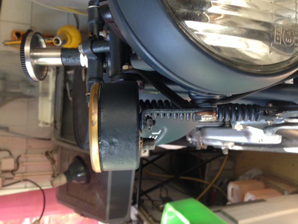
So onto fitting it. I'm always happy at the way these old bikes facilitate maintenance - it's so easy to pull the front wheel out with the bike on the front stand. Here's the speedo gearbox:


And here's the small pinion inside the brake plate. You have to remove the split pin and the pinion to get the gearbox off:


There's a bit of debris here, and some damage on the small pinion. I'm not sure the two internal pinions are mating properly.


Once you have undone the large locknut, you can unscrew the speedo gearbox. You'll see this split pin underneath the driven gear - remove the split pin and you can tap out the gear using a drift. It will drive out the cap:


The cap with the grease nipple is staked in, but will come out if you gently tap the driving pinion. You can now inspect all the components, clean and grease them before reassembly using a new split pin.


By the way, this is a different gearbox. Not my damage!

Monday, 5 September 2016

Missing Speedometer

One of the things that always seems to be missing from my projects is the speedometer. Fortunately I guess all my bikes have chronometric instruments, which do not attract the exorbitant prices of the PA speedos, but nevertheless they are not cheap!

The W/NG was no exception. Fortunately, the drive gearbox is there:


It works, but looks like it is full of crud; the small pinion 5246-38 is missing:


The big one is there though:


The gearboxes are easy to clean out. The two spindles are both retained in place with a pressed plug, a bit like the core plugs you might find in an engine block. The one on the end of the horizontal spindle, that goes into the hub has a grease nipple; the vertical one, that drives the cable is retained by a split pin.

These gearboxes are available in a variety of options:

  1. clockwise in/clockwise out
  2. clockwise in/anticlockwise out
  3. 12:8 ratio
  4. 14:8 ratio

And probably many others. They are quite straightforward to dismantle, though the cast bodies are brittle. Remove the split pin and tap the end of the cable drive spindle with a 1/4" punch - the spindle will push the plug out with it; do the same for the other spindle. clean all the old, hardened grease out and reassemble.


We'll have to buy a cable. It will have a spade type drive:


The small pinion is readily available from our favourite Suffolk spares stockist and is fitted after the gearbox is mounted in the brake plate. I used a split pin, making sure that the legs were trimmed short enough to disappear into the groove around the pinion


Here it is in place. You can see that when it is the proper position, the groove is enclosed in the brake plate and there is little space:


The speedo head is missing of course. I have bought this one from eBay:


It's in very nice, patinated condition and has a light and a trip, unlike the proper S433B military one; but this is more useful to me so would make a sensible choice.

It will need some brackets. 1942 bikes like mine have the separate speedo brackets (5213A-41 and 5213B-41) as shown in the 1943 parts book:


These are the brackets I need:


These are also shown in the 1941 parts book with a different illustration:


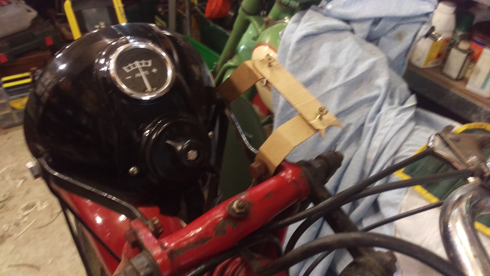
So to replicate these brackets, we will make some dummies with 3/4" wide strips of cardboard:


The strip with the two screws mimics the fixing screws on the back of the instrument:


Wondering if I have this rear bracket upside down. I've realised that it doesn't look like the parts book...


The 'upside down' theory seems to be born out by these excellent pictures of 'Burney' a fire-damaged W/NG being resurrected by Vincent van Ginneke of the AOMCC:

You can see that the speedo is at 90 degrees to the front leg of the girder


Top view shows relative position of speedo and headlamp
So let's try again:


Cut a slice of 3 mm thick cold rolled sheet steel, 16.7 mm wide as described by Vincent, not worrying too much about the length at the minute:


Its the bends that matter. Put the piece in the vice and make sure it is perpendicular to the vice jaws:


Two 45 degree bends give us the profile we need:


Clamped in place:


Two holes drilled for clearance on 1/4" bolts:


We will trim up and round the ends when we are finished. No point in doing that until we know it is in something like the right position. Here's my W/NG alongside Vincent's - looking very similar:


So here we have the second bracket, bent up and drilled:


And now, completed brackets waiting for paint.


Compare the W/NG at the museum. Looks like bracket is twisted; mine needs the corners removed!


And another view:


This one looks like it is further from the machine centreline:


Tuesday, 3 May 2016

Speedometer Clutch Repair

I have intermittent faults with my speedometer, as I may have mentioned once or twice - either sticks at zero or runs around to full scale and stays there. This is caused by the clutch slipping and leaving the camshaft either with the commander pinion engaged, driving the needle right round, or failing to engage the pinion at all, leaving the needle at zero. As with many speedo failures, this is caused by over lubrication.

The first step is to pull the speedo out. Fed up with trying to maneuvre my hands under the top yoke, I removed the headlamp first:


This means that you can remove the cable, the speedo lamp and the little M6 nuts securing the speedo into the yoke very easily.

This post is not going to be a speedo rebuild tutorial. There is a lot of that already on this blog, and more in my forthcoming book. No, this post is just to record the rebuild of the speedo clutch; this first step is to strip the speedo down to the movement and then take the movement apart for cleaning and inspection.


This is the clutch, disassembled with the parts in the correct sequence. I have cleaned them with methylated spirit and a brush.


They are lying on a sheet of white paper - very useful for cleaning wheels!

Monday, 27 February 2012

Watchmaker...

So with the odometer and the speedo drive sorted out, it was onto the movement and the case. This is the movement as it emerged from the case:

The movement appeared intact on inspection, indeed it was just caked in grease and the debris from the mangled drive wheel. It was a simple matter to strip it down, then we sorted the various assemblies into separate pots for cleaning with pegwood, solvents & the ubiquitous toothbrush. Look at the colour of the solvent:


This took several rinses, followed by polishing of the wheels & arbors.  There wasn't any tooth damage to the wheels, and the various pivot holes in the plates are all in good condition.


Reassembled & lubricated the speedo now works nicely in the electric drill.The picture below shows it in position in the main frame, hooked up to the main drive & the odometer. We cleaned the odometer wheels (very gently) with a swab dipped in a mild water/detergent solution:


Next stop was the case, which required a trip to the shed to find the top yoke, since there was no strap for the speedo and no idea of what it should look like. A cardboard template and some of the inevitable sheet metal work soon remedied that problem, and the case was rubbed down and sprayed gloss black. The picture below shows the speedo in position in the top yoke, from underneath:


The dial and needle we left mostly as found - we don't want to polish all the patina away. I had the lamp holder still attached to the original wiring harness, so this was polished up using brass brushes in the Dremel, wired up and fitted back in place. some new M6 nuts finished the job - since the design of these instruments originated in France, all the fasteners are metric.