Showing posts with label chronometric. Show all posts

Saturday, 7 December 2024

FH - speedometer

The chronometric speedometer that appeared with the FH kit is definitely not Ariel – I was told it is from a police spec AJS Model 31 CSR! The rim has a 3/8" piece removed from it which looks very tidy, definitely not a bodge – maybe it’s to allow a police workshop to remove the rim for recalibration easily? I have no idea if it works or not. 

So – in order for it to become a S467/195, which I believe it needs to be to suit my ’58 Huntmaster/FH, it will need:
  • An overhaul, including resetting to zero
  • A new dial
  • Probably a new rim.
Lastly it looks like the male thread for the lamp is spinning in the case – I guess it was swaged in or something, so that will need sorting out too.


As usual, I sent it to Russell Smalley at Chronometric Instrument Services - he's done all my speedos since the SQ4. His quality of work is excellent and very fairly priced.

It came back in about a week, thoroughly packaged:


It's got a used dial and needle, so that the appearance is in keeping with the odometer wheels. It's had a mechanical overhaul, new seals and rim, and a new bulb holder thread swaged in to the case:


Here it is going into the dashboard:


There's a stainless bracket I made for the indicator relay - which in this position makes it fiddly to fit the cable. I think there will be a bit more development needed here! 

Wednesday, 13 November 2024

FH - wiring the dashboard

 This will be the first time that I've wired up an Ariel with the separate instrument panel fitted to the swinging arm frame bikes with the headlamp nacelle. Looking at the wiring diagram it makes sense to wire up the panel separately from the rest of the bike, to be fitted later.

As you've seen, and in line with the wiring diagram, I have fitted a 5-way bullet connector between the main harness and the front end. Some of the cables from the instrument panel will go into this multiple connector, and others will stay on the panel whilst further connections will go into the headlamp. 

I made a start on the panel by fitting the ammeter and the light switch. I had the speedometer fitted as well, but found that the speedo lamp fitting was loose in the speedo body and the bulb holder could not be removed so I've sent this off for this to be repaired and the speedo overhauled.

Here's the initial layout. I've put all the wires in and crimped the ring terminals; the next step is to try this on the bike and see where the cable is going to route and how I can tie these cables together in sleeving.


This is the result. You can see I've terminated all the wires now, and added some sleeving and routed some of the wires around the top of the speedometer. I can't do much more until the speedo is back from Russell.

I need to clip the switch in and add the rubber ring around the switch and the ammeter, but it does work and I have both a rear lamp and a stop lamp. For some reason the horn doesn't work? 


It's alive!


Next stop on the wiring list is to add the combined horn button and dip switch. This is the original one and I have just removed the old wiring and clean the switch up with degreaser. More of that later.


Tuesday, 16 January 2018

Winter Work on the SQ4

It's time to think about winter jobs on the SQ4. The W/NG is the go-to bike and with no chrome makes an ideal machine for the winter, so if I can resist the temptation to tinker with it I can get on with the SQ4 and still have a bike to ride. The SQ4 jobs are:
  1. Fix the speedo and get the blurred dial replaced
  2. Get a new slow-running screw for the Solex
  3. Remove the indicators - I have decided to do this, because they look awful and because the indicators are regular tungsten bulbs and the load causes the LED headlamp to flash with the indicators. This is a bit disconcerting at night...
  4. Upgrade the headlight again
  5. Replace the front wheel bearings with sealed bearings
  6. Replace the front inner tube which leaks slowly
  7. Look at the brakes again as they bed in
  8. Make a new tool roll
  9. Fit a couple of transfers
  10. Change the oil tank for the one with a good filler neck thread
  11. Make a lower chain guard
I'll make a separate post for the chain guard. It's here.

But first, checking the bike over reveals that the horn doesn't work. A quick nose about with the multimeter reveals no supply at the horn, so we look at the 15A horn fuse. This is blown, and was probably too low for the horn so we will change it for a 20A. This works fine and consistently, so we will leave this for now. We'll also pull the indicator circuit fuse...


I've stripped out the headlight, in preparation for sending the speedo away, uprating the headlamp and removing the indicators.The speedo has gone to Russell at Chronometric Instrument Services for a clean, new springs and a new face:


And here it is, back again just over a week later:

Soundly packed with lots of bubble wrap

New face, all numbers in correct positions

Guarantee sticker on the back

New screws and nuts
Now we can put the headlamp shell back in place with new bolts:


This is the new headlight bulb and it's driver:


It's from CDRC, like some other bulbs I have bought and is their 5th Generation LED headlamp bulb shown here. Not cheap, especially as to fit it I needed an H4 reflector which I bought from Paul Goff as usual. It's the 7" Lucas reflector with a pilot bulb. The bulb is very nicely made - aluminium, powder coated black with nice elastomeric seals and good quality connectors. I've chosen a 6V bulb, so that I can keep the ignition & generating systems running at 6V.

The bulb fits into an adapter ring, which is provided with the bulb. This allows you to twist the bulb through 360 degrees, offering left, right or central dip:


Whilst the bulb looks quite long it appears to fit into the SSU700 shell quite nicely. The cable goes off to the driver box which I will mount in the bottom of the shell.


All done and back together:


One job that wasn't on the list was to fix the offside fork leg which sticks down over large bumps. I pulled it apart to find that it was actually sticking with maybe a third of its total stroke left unused, so now that I have eased some very tight new bushes I am looking for better behaviour from the front suspension! I checked the other leg while I had most of it apart, which moved freely.

Monday, 5 September 2016

Missing Speedometer

One of the things that always seems to be missing from my projects is the speedometer. Fortunately I guess all my bikes have chronometric instruments, which do not attract the exorbitant prices of the PA speedos, but nevertheless they are not cheap!

The W/NG was no exception. Fortunately, the drive gearbox is there:


It works, but looks like it is full of crud; the small pinion 5246-38 is missing:


The big one is there though:


The gearboxes are easy to clean out. The two spindles are both retained in place with a pressed plug, a bit like the core plugs you might find in an engine block. The one on the end of the horizontal spindle, that goes into the hub has a grease nipple; the vertical one, that drives the cable is retained by a split pin.

These gearboxes are available in a variety of options:

  1. clockwise in/clockwise out
  2. clockwise in/anticlockwise out
  3. 12:8 ratio
  4. 14:8 ratio

And probably many others. They are quite straightforward to dismantle, though the cast bodies are brittle. Remove the split pin and tap the end of the cable drive spindle with a 1/4" punch - the spindle will push the plug out with it; do the same for the other spindle. clean all the old, hardened grease out and reassemble.


We'll have to buy a cable. It will have a spade type drive:


The small pinion is readily available from our favourite Suffolk spares stockist and is fitted after the gearbox is mounted in the brake plate. I used a split pin, making sure that the legs were trimmed short enough to disappear into the groove around the pinion


Here it is in place. You can see that when it is the proper position, the groove is enclosed in the brake plate and there is little space:


The speedo head is missing of course. I have bought this one from eBay:


It's in very nice, patinated condition and has a light and a trip, unlike the proper S433B military one; but this is more useful to me so would make a sensible choice.

It will need some brackets. 1942 bikes like mine have the separate speedo brackets (5213A-41 and 5213B-41) as shown in the 1943 parts book:


These are the brackets I need:


These are also shown in the 1941 parts book with a different illustration:


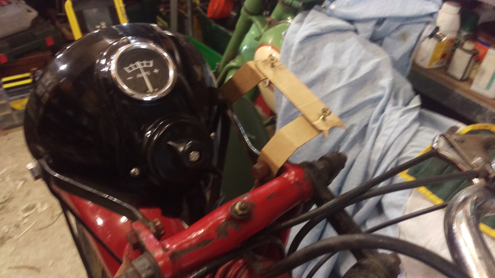
So to replicate these brackets, we will make some dummies with 3/4" wide strips of cardboard:


The strip with the two screws mimics the fixing screws on the back of the instrument:


Wondering if I have this rear bracket upside down. I've realised that it doesn't look like the parts book...


The 'upside down' theory seems to be born out by these excellent pictures of 'Burney' a fire-damaged W/NG being resurrected by Vincent van Ginneke of the AOMCC:

You can see that the speedo is at 90 degrees to the front leg of the girder


Top view shows relative position of speedo and headlamp
So let's try again:


Cut a slice of 3 mm thick cold rolled sheet steel, 16.7 mm wide as described by Vincent, not worrying too much about the length at the minute:


Its the bends that matter. Put the piece in the vice and make sure it is perpendicular to the vice jaws:


Two 45 degree bends give us the profile we need:


Clamped in place:


Two holes drilled for clearance on 1/4" bolts:


We will trim up and round the ends when we are finished. No point in doing that until we know it is in something like the right position. Here's my W/NG alongside Vincent's - looking very similar:


So here we have the second bracket, bent up and drilled:


And now, completed brackets waiting for paint.


Compare the W/NG at the museum. Looks like bracket is twisted; mine needs the corners removed!


And another view:


This one looks like it is further from the machine centreline: