Showing posts with label ignition. Show all posts

Monday, 12 May 2025

SQ4 - updating the ignition system

 The Square Four is on the bench at the moment for some maintenance and an electronic ignition conversion. 

I'm fitting an Accuspark system to see what advantages I can really gain. I'm led to believe that the bike will start more easily and will be smoother - I'm hoping that it may be slightly less rattly particularly in the coupling gears and I've also been told that running in town is better as the Hall effect sensor is less sensitive to the low voltage the dynamo provides at low speeds.

This is what you get in the kit - a new distributor base with the Hall effect sensor and 3 magnetic sleeves to go over the distributor cam. I understand that they are all the same magnetically but you use the one that fits best.

Here's the old setup - it works perfectly and is original. Starting is very easy so it will be interesting to see what I gain, if anything. I don't have to change anything permanently here: I can retrofit this system easily if I want to - I won't be cutting or removing any wires


There's two things to check in the battery box - one that it really is negative earth and two that I have removed the fuse to isolate the battery.


This is a useful view of the current cam and auto advance setup - you'll notice the odd springs. I don't think they're supposed to be like that but it's curious that I have a single spare spring in my box of ignition parts. Anyway, the second thing is that those rivets are raised compared to the body of the distributor and will foul the base plate of the new electronic ignition sensor so there is some work to do to provide clearance.


I've measured the diameter of the circle described by the rivets and marked it out on the base plate using a pair of odd-leg callipers, ready to cut a hole.


The base plate is actually quite thick - probably 2 mm or so. Since I can't find my Abrafile I have chain drilled inside the circle and will have to file it out. The housing is made from sheet steel set into thermosetting plastic and we don't want to crack it using some over-brutal method.


So that's it filed out quite neatly but we don't want to be too self-congratulatory at the moment do we! The problem is not obvious but actually it is not only the rivets in that ignition cam that are proud of the distributor body mounting face - that diamond shaped piece is also verging on being too high as well. I toyed with the idea of reducing the height of the whole cam assembly for a while but the real solution is to open the hole out again.


And as if by magic here it is, opened out to 40 mm. The difficulty that arises now is that the two M3 mounting holes for the sensor are very close to the edge of the hole and in one case the hole is no longer complete so I'll have to think of some other method.


The sensor was originally mounted on a little brass plate so what I've done is used that brass plate and the existing holes in the steel base plate to position a much larger brass plate that bridges the 40 mm hole in the base plate. I made the brass plate much too large but roughly the right shape and drilled for the two M3 holes for the sensor, fixing the brass plate into place on the base plate through the sensor holes. I then drilled two more holes outside of the large central 40 mm hole and fixed the new brass plate with two additional M3 screws. That way I could guarantee that the sensor would remain in its original position.


And here it is fitting nicely. The three rotating magnets are quite different shapes internally, and only one fits this cam - and it fits firmly.


And again we have the rotor arm in place and the distributor base plate screwed down.

I've temporarily wired it up for the moment - the red wire goes to the positive feed on the coil and the black wire goes to the contact breaker side of the coil. It will need some PVC tubing over the wires and some better quality eyelets, and I'm waiting for some thermal paste to use with the sensor and the brass plate but it will do for the purposes of testing. 

Hopefully I will get an opportunity in the next day or two to start the engine.

Post script: I started the engine on the 13th May, loosening off the distributor and retarding the timing to get it going; the Hall Effect sensor made an odd buzzing or fizzing sound which made me switch off in a hurry to check the wiring. The wiring was fine; the sensor wasn't tight enough on the baseplate which seemed to improve matters. It's still doing it and it sounds thermal. With the engine warm I advanced the timing to more or less where it had been before and went for a test ride. It's certainly smoother.

A few weeks later, and it's all working fine. The battery seems to be remaining at full charge most of the time now, so it appears that the ignition system is drawing less current than it used to.

Monday, 3 May 2021

QR50 - first start

Son Thomas came up to North Norfolk on his RE Interceptor for a play with the Ariel Huntmaster kit. After a spin along the coast (during which he managed to find  pre-installed fault on the W/NG's throttle cable nipple - we came back on the choke cable and a hand throttle) we repaired to the workshop to take a look at the QR50, which is almost finished.

I'd assured myself that the electrical system worked:


I used the big power drill to spin the generator and to prove the sense of the kill switch and the rear brake switch, and to prove the CDI unit worked. As I suspected, the kill switch and brake switch wires are both earthed to kill the engine - though the position of the brake switch doesn't seem to affect the spark. And how do I know this? Because it works!


Wednesday, 15 April 2020

QR50 - Generator Stator

Updated: first published March 2020

While we are in lockdown to slow the spread of Coronavirus, I have started to look at the QR50 electrics. It's pretty easy to solder up a new wiring harness in the office.

I'll write about the wiring harness in another post but first, before we start on that we need the stator casting repaired. You might recall I mentioned that it was toast and that I had bought a PA50 stator (complete) to replace it but that the PA50 stator does not fit...


Pictured here is the original stator, with all the wiring missing and the CDI sensor coil burnt out somehow. Fortunately the exciter coil is continuous, because the PA50 coil is bigger; the PA50 trigger coil however is identical to this one and will just swap out.


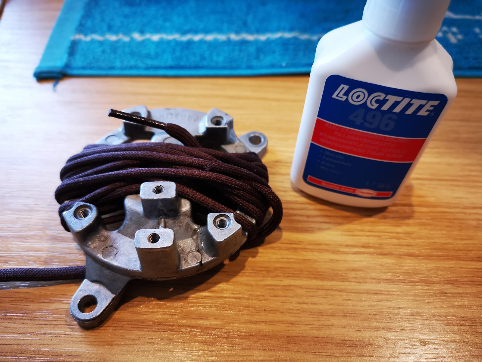
This is the back view. If you look closely at about 10 o'clock, you can see a crack in the casting. I did a little research on the Henkel website for a suitable cyanoacrylate that had low viscosity to wick into the crack and came up with Loctite 496, as a low viscosity adhesive specifically formulated for metals. Unfortunately the high temperature alternative, 4203, doesn't seem to be available anywhere so we will have to see how this goes.


Here's the crack, bound up with a bootlace...


And as if by magic, I now have a rebuilt stator. I've reused the existing exciter coil, which has just been gently cleaned. The trigger coil comes from the donor PA50 stator, and the wiring has been replaced:


Inboard view:


And here's the stator trial fitted in the offside crank case: