Showing posts with label solder. Show all posts

Thursday, 10 July 2025

SQ4 - under the tank

 I've taken the opportunity to remove the petrol tank because it's time I did the valve clearances and had a look at a persistent oil leak that has been going on for years. I thought it was fixed; I changed my mind and decided it was a head gasket problem - but then careful observation of the rocker box oil line revealed some seepage. It's obviously been quite bad in the past at some point, before I fixed it last time, because there's oil on the steering damper plates under the steering head. There must have been quite a jet to get it out there. 

Some years ago I did repair a leak here but it appears I didn't do it very well:

When I took this apart it was clear that they was some oxidization within the joint which had prevented the solder wicking down inside the fitting. I cleaned that up with wet and dry and tinned the pipe with some solder, using plenty of flux to sweat the joint into place. It resists that twisting now. 

The next job is to do the tappets and pulling off the rocker covers reveals some lovely clean valve gear. 

These are all supposed to be set to 0.001" with the engine cold. I used the famous 'Rule of Nine' to set them up. 

Valve clearances all proved to be very close to where they should be - I adjusted a couple of them but most of them were ok. I moved on to the spark plugs - cleaning them, checking their gaps but again they were all ok.


This one is from cylinder number 4, but it's fairly typical of all the others. You might think it's a little dark on the centre electrode and indeed we might consider adjusting the mixture a little. We could put another washer under the float valve to lean out the mixture across the whole rev range.

I took the opportunity to change the thumb nuts holding the HT cables to the plugs for some larger ones that I made some years ago.

With the rocker cover off I took the opportunity to snug down the head bolts and nuts. This is quite straightforward except for the pair that are buried in the fins - these two at the back are particularly difficult and you have to take the carburettor off to get at them. The one on the timing side of the bike is almost impossible because the casting has not been cleaned up sufficiently for you to be able to get at the nut.

Next time that I take the head off, there will have to be some grinding in there.

Reassembly was quite straightforward, apart from getting the oil tank back in. I've now 'adjusted' the area above the engine plate and below the frame rail with my favourite (small) hammer. It goes straight in now, but you have to remember to take the oil supply/return manifold off the engine first. You can't get the oil tank bottom bracket past the oil lines with the lines in place.

Thursday, 5 December 2024

FH - inching closer...

 The day seems to have disappeared again without too much workshop time but at least I've got a little bit done. 

The choke cable is now terminated to the right length, with a new nipple at the carburettor end. I didn't have the flat nipple that goes into the lever unfortunately and I didn't fancy making one on the lathe but I did have a little tiny one that goes in the choke slide.

There's not much to see here but at least we have a throttle slide and a choke slide that move independently of each other and don't have any slack in the cables.


The next little job is to make a couple of 5/16 CEI bolts to retain the finned exhaust clamps. Here I'm reducing some 0.445" stainless hex bar to the appropriate diameter for the bolts I need.


They're going to have a chamfer feature where they mate with the clamp - here is the chamfer on the clamp itself. When I have cut the thread on the bolt I will work out what the height of the bolt head above the clamp face needs to be:

That's all for a bit. I've got a 10-hour turn on the railway tomorrow which won't finish until after 11:00 at night, and then my grandchildren are coming for the weekend. Hopefully we will get the speedometer in the post either tomorrow or Saturday, so they'll be plenty to play with next week. I'll order the V-Reg2b voltage regulator as well, so we can convert the RB108.

Wednesday, 4 December 2024

FH - finishing the clutch

 Grabbing a few moments in the workshop, sorting out some knobs for the wardrobe I was able to give the FH a little bit of time clearing up the deck of the hydraulic lift and terminating the clutch cable. 

Over the years I've accumulated a collection of nipples and ferrules for cables along with a couple of adjusters and other bits and pieces which I keep in this little box.


The first job when terminating the clutch cable is to fix the pear nipple to the gearbox end, clamping the bare cable in the die and mushrooming the end, with the nipple in place of course.


You pull the nipple down to the mushroom the end of the cable holding it in the vise nipple down. Then you can use a large soldering iron to heat the nipple, dunk it in flux and apply some solder. Don't be tempted to use a gas torch because you will overheat the cable and ruin the temper. Probably the first time you will find out about this is when the cable breaks at a traffic light or while you're sitting behind a car.


If you are sparing with the solder you can make a nice little job without any extra work. You might need to run a file over the end of the nipple in case you've been a bit enthusiastic with the solder.


Hopefully you haven't got any solder on the shank of the nipple, stopping it fitting in the clutch lever.


I terminated the lever end at the handlebar with a brass nipple because I didn't want to use the diecast zinc nipple that was supplied with the cable. I have no idea whether the cable was properly terminated inside that nipple or not - perhaps I should cut it apart and have a look. 

Here's the bike as it stands today - I'm going to have to buy a new clutch dome or at least replate the original one shown here. For some reason the screws won't tighten down on the dome - it appears that they are a fraction too long or are expecting to use shake proof washers.


Friday, 3 June 2022

SQ4 - Oil Leak from the Rocker Feed

 This may be a seminal moment in the history of my SQ4. For years it's had an oil leak which I have always assumed to be poorly sealed pushrod tunnels at the head joint. However, having addressed a problem with a leak from the oil tank cap, something else which it has always done, I resolved to look at the drip from the rocker feed pipe. 

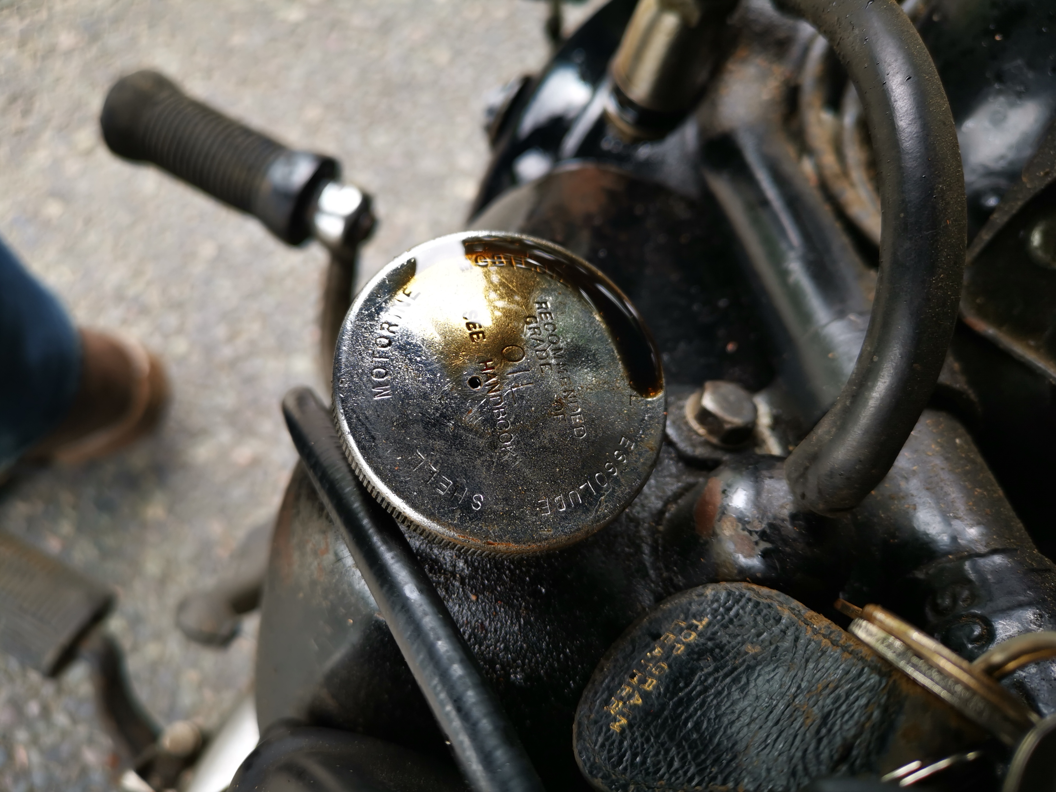
The oil tank cap has always had a weep from the breather:


Which translates to a wet leg on a long, fast run:

Looking at that first picture, I got to wondering why the cap has a vent hole when the tank has a piped breather that I have taken past the rear wheel. Surely the cap should be sealed?

It turns out that Square Fours don't use the same cap as other Ariels. I noticed that the 1951 SQ4 parts list has a -32 number for the cap - most bikes (other than Square Fours) I've seen use a -29 number. Maybe 5854-32 has no breather hole.

A blob of solder will sort it.

Onto the rocker feed. I ran the engine cold (75 psi on the gauge) and as the oil warmed up the leak appeared:

Now, my bad - I forgot to take a camera to the workshop when I fixed it. It turned out the tube was not pushed into the fitting at all - it was just held in place with a fillet of solder at one end, and had been like that for years - probably eight years. It's been leaking for most of that.

All fixed now.

Friday, 2 July 2021

FH fuel tap

The Owner's Manual for the FH describes, in several paragraphs, how to operate the fuel tap and makes it very clear that the tap specified was not the usual two-plunger tap used by Ariel since before the war. In fact the manual tells you to pull the plunger to turn on the main supply, and then to twist and pull it again to get reserve. It took me a few eBay mistakes before I found the right one, courtesy of John Mitchell of the AOMCC. 

The tap John sold me was in great shape, but it was missing the filter and the main supply pipe which draws the main supply from a point above the water in the bottom of the ethanol-laden fuel. Since I have other taps with this pipe, and I have made several filters, it was no problem to make the missing parts.

I started with a bit of 3/16" copper tube which I annealed with the wonderful Rothenburg Superfire torch. I set the tube up in my cable nipple swage:


Using a centre punch & a pin punch, I belled out the tube until it was a tight fit in the register machined in the tap.


Next step was to make a little cylinder on the lathe to position the pipe within the filter. This is machined internally to fit the tube and externally to the same diameter as the filter, and soldered in place at the top end of the tube:


So there we have it, the components of the tap:


To assemble the tap, I pushed the swaged end of the tube into the register machined in the tap body - I didn't attempt to solder it in. I then pushed the tube into the filter, and applied some flux to the tap body where the filter sits and around the cylinder I made earlier, through the filter gauze.

When soldering the filter onto the tap body, you need a fair bit of heat - I use my kitchen blowtorch for those sort of jobs.

You'll notice the tap has a fibre washer - I usually use Dowty washers in this application, but there was no way the plunger was going to 'fall easily to hand' with a Dowty washer on the tap - so a thinner fibre washer it had to be.

Tuesday, 28 April 2020

QR50 - Wiring

It's a bit early to be looking at wiring up the QR50, but since we are on lockdown and my workshop is a few streets away I have resorted to bringing stuff to the house to work on. It's good to bring the wiring indoors - it's a nice clean job that you can do at your desk in the study.

This is virtually all I have, apart from the toasted generator stator I showed you in another post. This is the CDI unit:


And here it is again with all that insulating tape removed. If you look closely, you will see that some of the wires have been cut very short:


This is the whole 'harness', minus the sleeving. There isn't much to wire up on a QR50, but it is not supposed to look like this:


Before we start though we need a circuit diagram. Through a lot of research, Honda parts lists, generic CDI system diagrams and looking at the charred remains of the original loom I have come up with this:


There's a lot going on in this diagram, besides the connectivity of the various parts. Let's look at the way the system functions:

  • The Black and White wire (BW) wire is the exciter - it provides AC voltage to the CDI module
  • The Blue and Yellow wire (UY) is the trigger - it uses the hall effect sensor in the rotor to tell the CDI unit when to fire the coil
  • The kill switch earths the exciter coil through a second BW wire, preventing the ignition from working.
  • The Green and Yellow wire (GY) is connected to a micro-switch in the rear brake lever. According to the user manual, the engine won't start if the brake is not applied, and there is a spring loaded lever to hold the brake applied while you start (this disengages as soon as you squeeze the brake). I assume (at this point) that the switch is intended to break a ground connection when you apply the brake, but that this has no effect when the engine is running...
  • The Black and Yellow wire (BY) is the wire to switch the ignition coil.
  • The Green wires (G) are grounds.
In addition to the functionality, I have used this diagram to indicate cut wires - each cut wire has a number (1 to 16), and each cut wire has a connector (male, female or double female). The harness layout is shown in a simple sketch with rough dimensions; I have shown a length against each cut wire and summarised these to determine the total length of each colour. This list, along with the list of connectors, tells me what to order. I have followed Honda's practice of using the same 1.0 mm² wire throughout.

I'm going to use original type Japanese 3.2 mm bullet connectors throughout. These work beautifully and are protected from the weather - but you must select them according to the wire diameter.


Here are most of the parts we need:


First, I am using some tube crimps and solder to extend all the wires from the CDI unit to match the only remaining original wire, the ignition trigger. This is often tricky, as 40 year old wires are often too dirty to solder; this one has been OK, probably thanks to all the insulating tape.


I've protected these joints with heat shrink sleeving. I bought a selection of 8" lengths in various colours from eBay, and very useful it is too.


This is the CDI unit, finished with sleeving and boots as the original was. That large boot with the section change was made from a short length of heat shrink sleeving, partially shrunk over a small bottle of glue:


The parts list calls for a harness from the CDI unit leading up to the headstock area - this connects in the two handlebar switches.


Here's the finished stator:


Now I have the bike partly assembled, I can lay the harness out on it to see where the parts are routed and to ensure that I have sufficient length in each of the harness parts.


Wednesday, 15 April 2020

QR50 - Generator Stator

Updated: first published March 2020

While we are in lockdown to slow the spread of Coronavirus, I have started to look at the QR50 electrics. It's pretty easy to solder up a new wiring harness in the office.

I'll write about the wiring harness in another post but first, before we start on that we need the stator casting repaired. You might recall I mentioned that it was toast and that I had bought a PA50 stator (complete) to replace it but that the PA50 stator does not fit...


Pictured here is the original stator, with all the wiring missing and the CDI sensor coil burnt out somehow. Fortunately the exciter coil is continuous, because the PA50 coil is bigger; the PA50 trigger coil however is identical to this one and will just swap out.


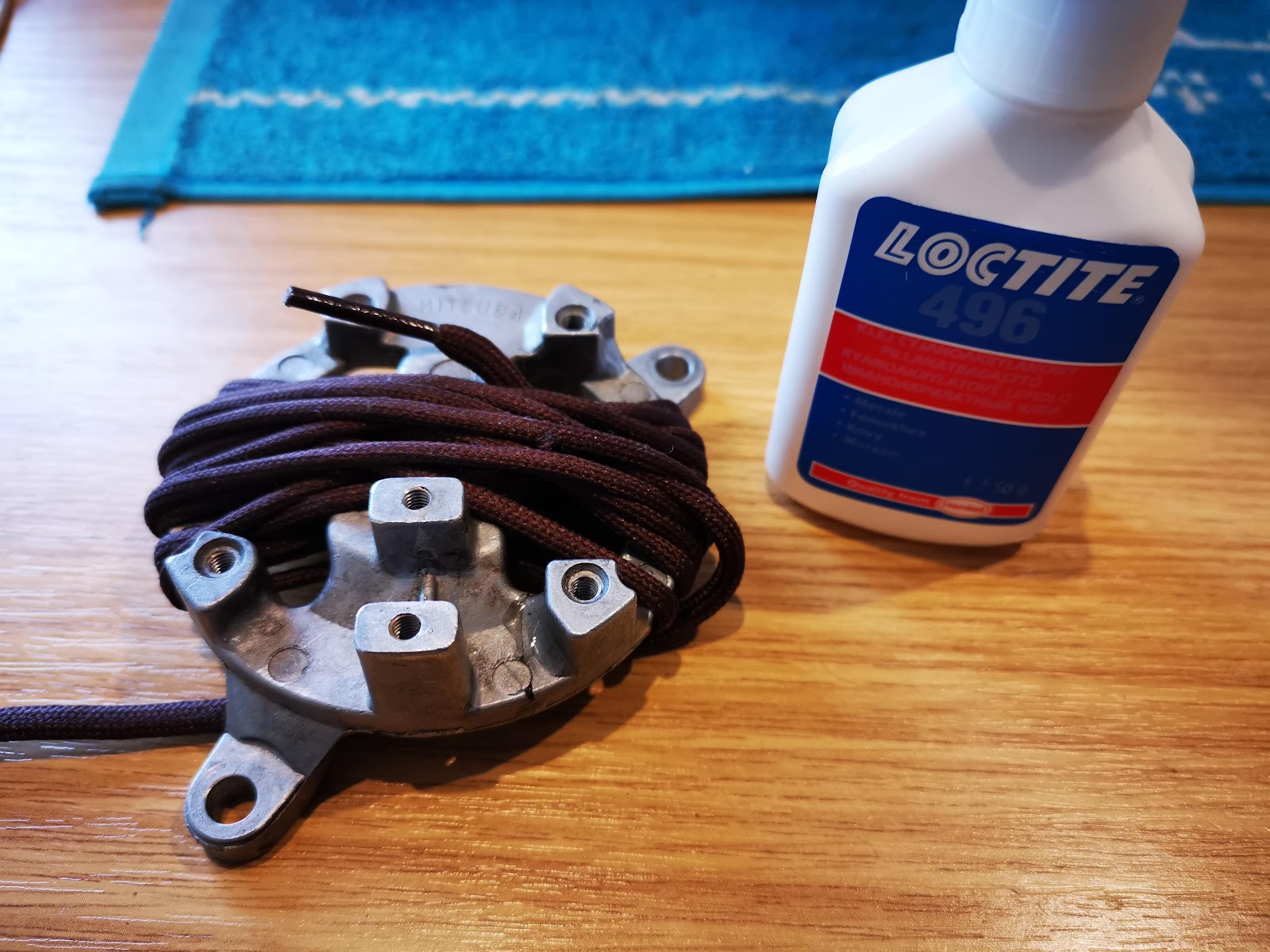
This is the back view. If you look closely at about 10 o'clock, you can see a crack in the casting. I did a little research on the Henkel website for a suitable cyanoacrylate that had low viscosity to wick into the crack and came up with Loctite 496, as a low viscosity adhesive specifically formulated for metals. Unfortunately the high temperature alternative, 4203, doesn't seem to be available anywhere so we will have to see how this goes.


Here's the crack, bound up with a bootlace...


And as if by magic, I now have a rebuilt stator. I've reused the existing exciter coil, which has just been gently cleaned. The trigger coil comes from the donor PA50 stator, and the wiring has been replaced:


Inboard view:


And here's the stator trial fitted in the offside crank case:


Monday, 13 January 2020

CX500 - Fixing wiring...

There have been a few posts on the CX500 recently, and hardly anything on my Ariels. The W/NG is on holiday with my son; the FH is waiting time and the SQ4 is running around Norfolk as the daily rider since I fixed it's clutch.

After it's test run, where we found a starting problem and non-functioning tail lights it has been back in the workshop for this mess to be fixed:


Most of this is damage to several splices in the main harness, visible as black dots in the wiring diagram:


To get access to this, I have removed the tank and the headlamp cowl. This has let me strip the harness covering back to get good access to the damage:


Stripping the conductor insulation, the copper is too corroded for soldering so the splices will have to be crimped. This is why I always build a new harness for my ground-up restorations:


Repairing the splices is not a huge problem - just crimps and heat shrink sleeving:


I've re-covered the harness with split sleeving for the movement, which is easy to re-open if there are more faults that are going to emerge. We shall see.

Since I have the front end apart I have had the chance to align the cable and harness routing with the drawings in the manual:


Honda manuals are excellent for this. This diagram shows the brake hoses and other cables:


This one shows the engine and battery wiring:


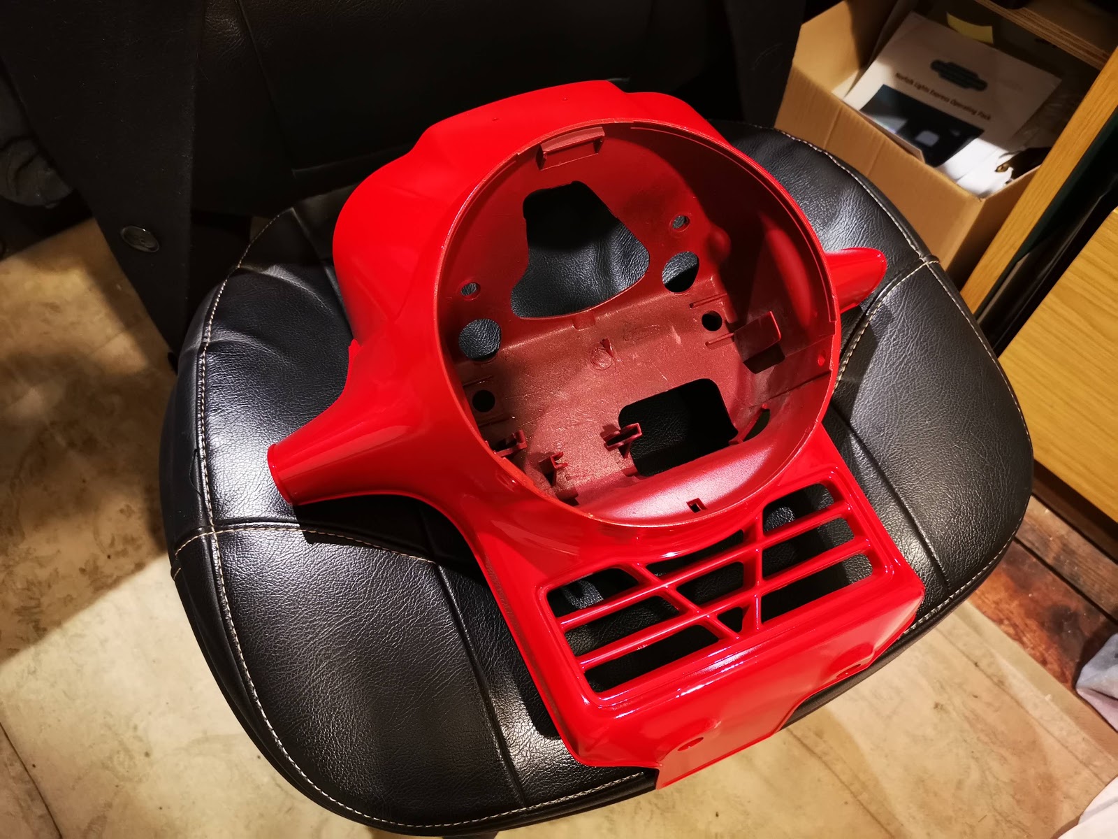
Secondly, I have repainted the headlamp cowl using RS Paints Honda Helios red:


This isn't cheap, but it is excellent paint.


I've also repainted some of the black components in the area:


I masked up the idiot lights - they are glued in place at the factory: