Showing posts with label crimp. Show all posts

Tuesday, 4 February 2025

FH - fuel line

 Here it is, burbling away at the top of the road looking marvellous:


The brakes are a little better but still don't inspire much confidence. I have adjusted them again but it's likely that we will re-line them when the wheels come off again. I've also corrected a slight misalignment in the rear wheel.

Keen eyes will note it's still wearing the temporary fuel tank in this picture - it's time to make a fuel line. These are the bits we need - some 1/4" fuel pipe, two ferrules, fittings for each end of the line and the little swage we made years ago from two bits of 1/2" square bar:


Fit the ferrule over the end of the fuel line and push the fitting in, being careful to orient it to suit the natural bend in the pipe:


Put the two halves of the swaging tool around the ferrule and nip it up in the vice. When you are happy that it's all in the right place, give it a little squeeze but don't fully close the swage; then turn the ferrule through 90° and squeeze it again. Doing it all in one go will probably split the ferrule on two sides.


There we go - nice neat job:


And back on the bike. The pipe could probably have done with being 1/4" shorter but it is tidy enough for now.


Tuesday, 28 April 2020

QR50 - Wiring

It's a bit early to be looking at wiring up the QR50, but since we are on lockdown and my workshop is a few streets away I have resorted to bringing stuff to the house to work on. It's good to bring the wiring indoors - it's a nice clean job that you can do at your desk in the study.

This is virtually all I have, apart from the toasted generator stator I showed you in another post. This is the CDI unit:


And here it is again with all that insulating tape removed. If you look closely, you will see that some of the wires have been cut very short:


This is the whole 'harness', minus the sleeving. There isn't much to wire up on a QR50, but it is not supposed to look like this:


Before we start though we need a circuit diagram. Through a lot of research, Honda parts lists, generic CDI system diagrams and looking at the charred remains of the original loom I have come up with this:


There's a lot going on in this diagram, besides the connectivity of the various parts. Let's look at the way the system functions:

  • The Black and White wire (BW) wire is the exciter - it provides AC voltage to the CDI module
  • The Blue and Yellow wire (UY) is the trigger - it uses the hall effect sensor in the rotor to tell the CDI unit when to fire the coil
  • The kill switch earths the exciter coil through a second BW wire, preventing the ignition from working.
  • The Green and Yellow wire (GY) is connected to a micro-switch in the rear brake lever. According to the user manual, the engine won't start if the brake is not applied, and there is a spring loaded lever to hold the brake applied while you start (this disengages as soon as you squeeze the brake). I assume (at this point) that the switch is intended to break a ground connection when you apply the brake, but that this has no effect when the engine is running...
  • The Black and Yellow wire (BY) is the wire to switch the ignition coil.
  • The Green wires (G) are grounds.
In addition to the functionality, I have used this diagram to indicate cut wires - each cut wire has a number (1 to 16), and each cut wire has a connector (male, female or double female). The harness layout is shown in a simple sketch with rough dimensions; I have shown a length against each cut wire and summarised these to determine the total length of each colour. This list, along with the list of connectors, tells me what to order. I have followed Honda's practice of using the same 1.0 mm² wire throughout.

I'm going to use original type Japanese 3.2 mm bullet connectors throughout. These work beautifully and are protected from the weather - but you must select them according to the wire diameter.


Here are most of the parts we need:


First, I am using some tube crimps and solder to extend all the wires from the CDI unit to match the only remaining original wire, the ignition trigger. This is often tricky, as 40 year old wires are often too dirty to solder; this one has been OK, probably thanks to all the insulating tape.


I've protected these joints with heat shrink sleeving. I bought a selection of 8" lengths in various colours from eBay, and very useful it is too.


This is the CDI unit, finished with sleeving and boots as the original was. That large boot with the section change was made from a short length of heat shrink sleeving, partially shrunk over a small bottle of glue:


The parts list calls for a harness from the CDI unit leading up to the headstock area - this connects in the two handlebar switches.


Here's the finished stator:


Now I have the bike partly assembled, I can lay the harness out on it to see where the parts are routed and to ensure that I have sufficient length in each of the harness parts.


Monday, 13 January 2020

CX500 - Fixing wiring...

There have been a few posts on the CX500 recently, and hardly anything on my Ariels. The W/NG is on holiday with my son; the FH is waiting time and the SQ4 is running around Norfolk as the daily rider since I fixed it's clutch.

After it's test run, where we found a starting problem and non-functioning tail lights it has been back in the workshop for this mess to be fixed:


Most of this is damage to several splices in the main harness, visible as black dots in the wiring diagram:


To get access to this, I have removed the tank and the headlamp cowl. This has let me strip the harness covering back to get good access to the damage:


Stripping the conductor insulation, the copper is too corroded for soldering so the splices will have to be crimped. This is why I always build a new harness for my ground-up restorations:


Repairing the splices is not a huge problem - just crimps and heat shrink sleeving:


I've re-covered the harness with split sleeving for the movement, which is easy to re-open if there are more faults that are going to emerge. We shall see.

Since I have the front end apart I have had the chance to align the cable and harness routing with the drawings in the manual:


Honda manuals are excellent for this. This diagram shows the brake hoses and other cables:


This one shows the engine and battery wiring:


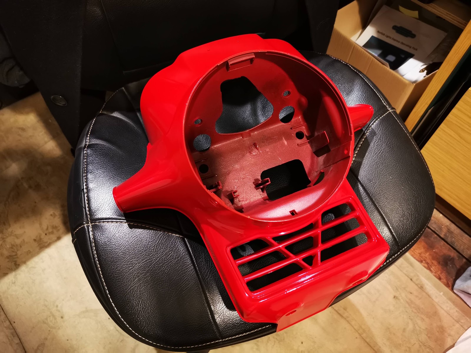
Secondly, I have repainted the headlamp cowl using RS Paints Honda Helios red:


This isn't cheap, but it is excellent paint.


I've also repainted some of the black components in the area:


I masked up the idiot lights - they are glued in place at the factory:

Saturday, 2 August 2014

Crimps

Time to make up some fuel lines. I've got 14" of 1/4" ethanol resistant fuel lines knocking around, and some suitable crimp ferrules.


To make a good crimp, you need a little tool which you can buy or, with a bit of 1/2" square barstock you can make your own. The tool is just two 2" lengths of 1/2" square bar, clamped together and drilled for a 1/2" hole, such that there is a semicircle in each bar. V shaped grooves have been filed at four positions around the outside of the hole, and two short 1/4" rods set into the two halves of the tool maintain alignment.

Cut the end of the fuel line square with a sharp blade. Slip the ferrule over the end and push the banjo, tee, or hose tail (with the union nut in place) into the hose, as far as it goes. The fuel line, normally 1/2" OD, will swell out to something like 17/32".

Place the two halves of the tool around the ferrule and squeeze in the vice. The ferrule compresses the tube back to about 15/32", thus retaining it on the hose tail. It produces a better crimp if you squeeze it half way, and then rotate the ferrule/hose assembly 90 degrees in the tool, then finish the crimp.


Compressing the ferrule to less than its original diameter generates some 'spare' material, which swages out into the V grooves we cut. Here is the fuel tap end:


Here is the carburettor banjo:


And here is the non-standard 1/4" fuel filter. Judging by the cr@p I get out of my Bantam tank we will need this: