Showing posts with label front brake. Show all posts

Monday, 22 June 2026

Mini-lathe - front stay spacers

 The mini lathe proved its worth again today and gave me two useful parts from some scrap.

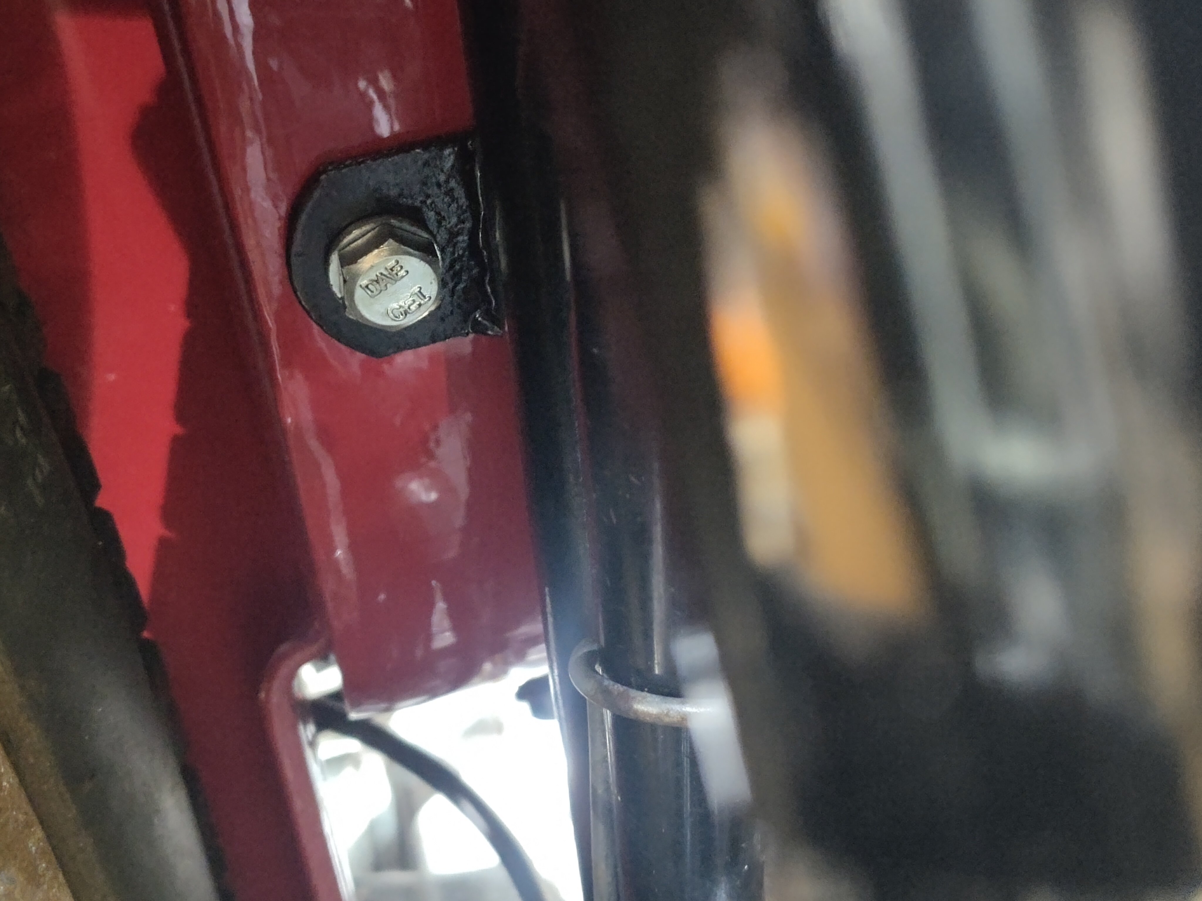
These are 3/4-in diameter by 3/16-in thick spacers for the Model A and the W/NG, with 6.5 mm holes to clear quarter inch screws.

Here is where they fit - what they do is give you a little bit more room between the fork leg and the mudguard stay to stop the brake rod rubbing.

They will be chemically blacked in the next batch.

Tuesday, 21 January 2025

FH - more brakes

 Moving on to the front brake, it's time to unearth the mysteries of the full width hub. This is the view from the parts book:


It looks like the brass bearing retainer used in the half width hub is still there but now has a sheet steel ring riveted to it retaining a small felt grease seal. This one has been a bit butchered and the steel ring is loose:


The one on the other side is still in place. That tube passes through the bearing and acts as a centralising mount for the brake plate:


As might be expected, there's a thin coating of rust on the drum, easily cleaned with various abrasive papers.

This spacer fits over the tube in the previous picture, between the brake plate and the fork leg. It was stuck in the fork leg - I guess there is some paint to clean out.


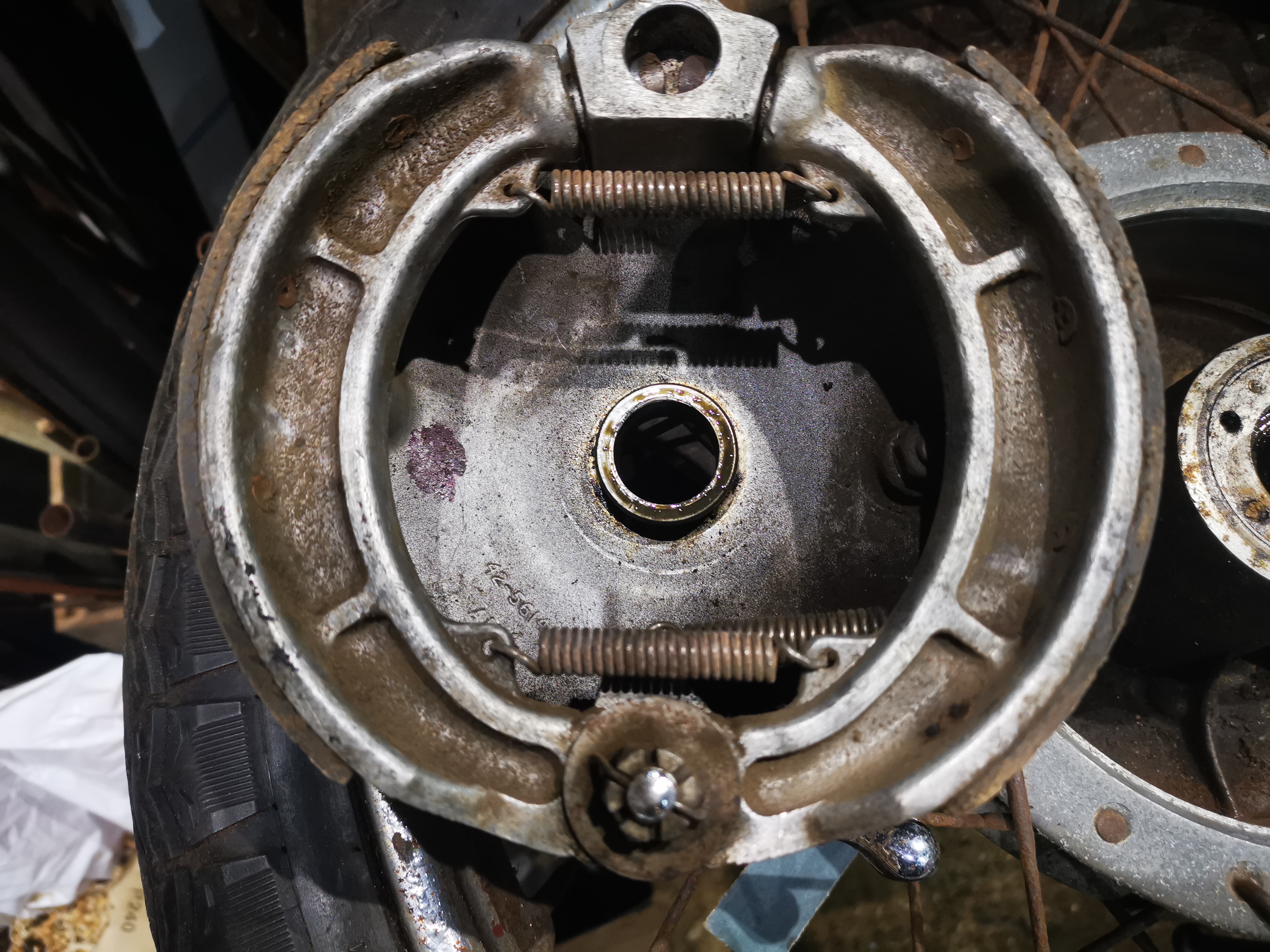
Both the shoes are glazed. This is the trailing shoe:


This is the leading shoe, though there is no lead-in chamfer:


As we found at the rear, the parts are all present and in good shape - but no lead in chamfer:


As an aide-memoire, while I clear out the paint from the front axle clamp in the fork leg, note that the drain plug is missing and there is obviously no oil to damp the fork movement!

Next job is to add a lead-in chamfer to both shoes and to reassemble & retest. After that it's:

  1. Fit the tank knee rubbers and aluminium trims
  2. Fit the tank, not forgetting to soak the fuel tap first
  3. Sort out the wiring routing under the dashboard and find the dashboard fixing screws
  4. Replace the rims and spokes when the tyres turn up.

Thursday, 12 December 2024

FH - a little more progress, and a big step...

 Well there's been a little bit more progress today. First off, I've finished the second of the finned exhaust clamp bolts:


Secondly I've been talking to people in the club about tyre sizes and whether I can get my desired tyre (Avon RoadRiders) in the size that I want. Having a look at the distance between the tyre and the chain guard reveals around 3/8" to 1/2" but also that this tyre, an Avon SM Mk11, is actually a 325-19. The front tyre, a Dunlop TT100 by the way is a 90/90-19 or 3.60-19. They are both from the 1980's.

I am hoping to buy Avon RoadRider tyres but unfortunately they are not available in the right sizes for this bike. The options appear to be to use a 100/90-19 for the rear (Avon's recommended replacement for a 350-19) and a 325-19 (original size) or a 90/90-19 for the front.


The next bit of progress is very small - it's just a P clip for the front brake cable. I've attempted to adjust both brakes but right now the front tyre is in the wheel clamp.


Lastly and very quietly and secretly I have hooked up the temporary fuel tank to the carburettor and started the bike. Unfortunately it will only start using Easy start, but at least it starts and runs. There may be some problem with the fuel supply or with the float bowl. It runs and returns oil and it runs nice and quietly so now I know that I have the HT needs the right way round, and the oil system is working properly, and the valve timing is correct and the ignition timing is more or less correct though it does spit back through the carburettor.

I think we'll have to wait 'til Monday to have another chance at it, but sleeping on it and looking at some of my pictures suggests that the float bowl gasket is missing. This will give you an air leak in the pilot fuelling circuit...

Monday, 2 December 2024

FH - little bits

 A short visit to the workshop today got a few little bits done. I've removed the oil tank and fitted a bolt into the seat base above it, and I've tightened up all the seat bolts now so that is secure. Unfortunately in putting the oil tank back I cannot refit all the earth cables - I will have to remove the toolbox again to be able to get to the bolts. I do however have to order the voltage regulator to rebuild the RB108, so that will entail removing the toolbox.


Tidying up the bench I did manage to find the inspection cap for the gearbox so I have given that a bit of a polish on the wheel and refitted it.


I've terminated the HT cables and fitted the plugs so they are ready for first start - so that's oil, sparks, compression and a kickstart. All I have to do now is bolt the carburettor in place properly with some gasket sealant and I will be able to connect up a temporary fuel supply and give it a kick. 

This next bit is the rubber cable tie for the front brake. It doesn't fit properly because my mudguard with its repairs is thicker than was originally intended so what I've done is to increase the width of the groove in this rubber piece, so it should now fit.


The last bit today is just to record that the frame clip behind the oil tank has a new half inch long bolt specially made to complete the fitting of the oil tank.

Friday, 28 May 2021

Model A - front brake rod

 The Model A came with its original front brake rod, but none of the fittings. It's an odd design - the rod is 3/16" (0.1875") but, to prevent rotation in the brake arm, it's flattened at the end. This makes it larger - it's actually threaded 1 BA, on a major diameter of 0.209".

Of course, cleaning up the thread is a bit of a challenge with the flat since many dies will not bite having three sets of flutes, or very narrow flutes, as the thin rod disappears into the gaps. 


Here's my stock 1BA die:


See the narrow flutes? This next picture is another I bought:


The flutes are much wider on this one, and I managed to recover the thread and get my newly-turned adjuster knob to fit. It's made from 303 stainless steel on the lathe, milled for detent on a 1 BA mandrel in the toolpost:


The outside is cut with a deep straight knurl, slightly chamfered:


The next lathe job is the spring housing, copied from the one on the W/NG. It's a bit of 1/2" 303 round bar with a 1/4" CEI thread in one end, bored 9.5 mm for clearance on the 3/8" brake rod end:


Tuesday, 9 June 2020

QR50 - assembling the forks

We are approaching assembly time on the QR50 build now, and it will be nice to get it off the bench and to get back onto the Huntmaster. It's been fun and it will be a smart little bike from which I have learned a lot, but I have too many projects at the moment and I want to see the Grandchildren riding this one.

So, while I wait for the gasket set, and for some time to start on the tinware let's assemble the front end. I've used the hone I made to clean the paint out of the yokes, and I use an M8 bolt and a bit of sheet metal to open the clamps a bit, so I can slide the new stanchions in. This is simple, though the balance on the bench is now a bit front-heavy. I hang a big weight on the back.


Looking at my handiwork I notice that the top yoke hits the oil filler - so that was why it was dented on both sides. If you look at this picture, you will see the reason - the steering stop is bent out of the way:


That's easily fixed with an adjustable spanner.


Next, I can assemble the front brake and put the wheel on. It looks great.


Saturday, 15 February 2020

QR50 - Brake plate stop

Last major job on the fork sliders is to weld on the stop for the front brake plate. For convenience, I have retrieved this from the old slider:


I've set up the whole assembly in the vice to ensure that it is welded to the new slider in the right place:


With it set up like this I can tack it in place. I can then remove the brake plate, and set the welder up for a fillet; the key element is to make sure I can access the weld:


With sufficient stick out and the gas pressure raised enough to keep the electrode cool, I can use some filler to complete the weld. Any excess is cleaned up with a round file. It fits beautifully:


Saturday, 1 February 2020

QR50 - Front brake

The front brake of the QR50 is a 3" half width, single leading shoe drum brake, pretty straightforward:


The one I have is very standard and is even painted gold - I just have to clean it up, paint it and re-attach one of the linings:


I've not seen this spring arrangement before:


Half an hour on the wire wheel has it looking much better:


Thursday, 15 February 2018

SQ4 Front Brake

As part of winter maintenance, I have my front wheel off for new bearings, a new tube and a look at the brake. It appears that I still haven't got it right.

Take a look at this, it is the leading end of the trailing shoe:


To me, this is indicating that I haven't got the adjuster tight enough - there is about 20-30% contact on both shoes, at the cam end - in both shoes, there is no contact at the adjuster end. Here is the leading shoe, trailing end:

In both cases you can see where the lining is worn by contact with the drum. The brake is nothing like as effective as the one on my W/NG, which is obviously a much lighter bike but the brake has much more feel. They are bedding in at the cam end (trailing end of the trailing shoe here):


I'm happy to see that the drum is nice and clean, with no trace of grease


Less happy to see the heat damage to the paint, but we will deal with that when the weather warms up.

Setting the drum up with emery tape and double-sided sticky tape in the traditional way results in much better contact. By the way, don't do this with one of the wheel bearings missing since the spindle, and the brake plate and shoes will not be concentric with the drum:

Set the brake plate up such that it is pulled down to the bearing and is held rigid (as far as possible with these pressed steel brake plates) - that way the shoes will be as cylindrical as possible. I've used a short tube spanner on the spindle to take the place of the fork leg, and I am holding the brake plate from turning with a tommy bar. I turn the wheel to sand the linings.

Start with adjuster backed off and gradually wind it in, turning the wheel a few times and then dismantle again for inspection. When your satisfied that the adjuster end of the shoes is ground down enough to fit the drum, put a bit of pressure on the brake cam lever and repeat. Stop when you have contact over most or all of the shoe.


Here's the leading end of trailing shoe:


Leading end of leading shoe

 Lots of dust after the process is complete:

Friday, 21 April 2017

Sorting the front brake rod

Two brake levers: the top one is a Drags repro and very nice it is too; the bottom one is the original one from my bike, which has a fully round hole for the brake rod. This obviously allows the brake rod to spin when you are trying to adjust the brake, which is irritating.


This hole is not supposed to be round...


This is a very dodgy picture, nicely illustrating the problem of focusing on small subjects while confusing the auto-focus with a confusion of adjacent objects. It shows the brake rod with a small weld, partially closing the hole on each side. I use MIG wire as a filler for jobs like this. 


After welding, I filed the hole back to shape to fit the brake rod. Here it is in place:


Job done. Now I can adjust the brake easily.


Sunday, 6 December 2015

Front Brake again

As you all know I've been having trouble with my front brake on and off since my SQ4 went back on the road late last year. This year it has had a lot of attention, and is a lot more effective than it was.

Yet it still 'groans' particularly when reversing but also moving forward, which is probably down to the cable being a little tight and the shoes still bedding it in.

However, I wanted to check with members of the AOMCC forum if anybody's brake plates bend outward (in the direction of the arrow) by a few mm when the brake is applied. This is quite easy to see in the garage. I'm guessing that's not normal.


Something is maybe not as square as it should be. Maybe the brake shoes are able to move out of true, or the hub is slightly conical? Maybe there is some play that should not be available?

The brake shoe linings may have worn lopsided and when force applied the brake plate springs a bit. They are not actually that strong, and normally don't have to resist much force along the line of the axle axis. The shoes may have worn unevenly. The springs may be distorting the way they sit, or the plate may be too close to the wheel hub. Something wrong with the bearing installation.

So I stripped it down again. What I didn't expect was two cracked shoes...


Given that these shoes have a marginally smaller diameter than the drum, and have an adjuster at one end that allows the shoe to be brought into contact with the drum, it's easy to see how this would happen.

The story goes like this. If you do the adjuster up relatively tight, the slightest movement of the shoe brings the friction material into contact with the drum. If there is a gap between shoe and drum at the cam end of the shoe, but none at the other end operation of the cam will attempt to bring the cam end of the shoe into contact with the drum, bending the shoe about the contact point at the adjuster end; the resulting bending moment causes a tensile load on the inner diameter of the shoe, leading to brittle fracture due to the hardness in the casting.


While this brake design is used in every car drum brake I have ever seen, it is invariably with fabricated steel shoes which will be considerably tougher than this cast aluminium.

Splendid club the AOMCC. Not more than a few hours after posting the story of my plight on the forum, Paul Jameson had put these in the post!


Many thanks Paul. I also have this from Draganfly, in exchange for my previous, silver painted version:


So the next step is to fettle it all to fit and get her back on the road.