
I'm beginning to wonder if buying old motorbikes is just an excuse to make stuff in the shed - the QR50 has had so many hours put into such a low value machine that I am beginning to wonder if it will ever end. So here I am with my first proper vintage bike - one that even the specialist Ariel suppliers hardly cater for, with the exception of course of the Ariel Klub Slovakia and this promises to be a veritable feast not only of turning, fabricating and welding but also for sewing and a new skill, leatherwork.
It's also together, patinated and has some history. I've been in touch with the VMCC Central Scotland section to see what they know about this bike, since it comes from their patch and has hardly travelled.
So, how to approach it? In case you have forgotten, here it is:

So as you can see, it is pretty much original. All the bits you can see are period and most of them belong to this bike; the front mudguard is from the next generation - it is post 1930 and is the valenced front guard fitted to girder forked models after 1931, so it is in-period and may well have been with this machine for a long time. It is not, as I have written elsewhere, an example of the similar guard fitted to the front of my SQ4 - which is of course fitted with a telescopic fork.

So once again, like the W/NG, we have a patinated period bike with all original bits (matching numbers) and this one even has it's original registration - this is a real treat and has to be treated with respect. We will be following the 'repair and make safe' approach we did with the W/NG, collecting and repairing missing parts and where we have to refinish (heat damage from welding for example) we will attempt to do so while blending the original finish. We are very lucky in that the tank is in very good shape - but it also introduces a bit of a quandary, since the chrome tanks have a superb black finish lined gold & blue, with areas of chrome exposed, and this black finish really makes the bike look the dog's dangly bits. Here's a 1930 Model G, the top of the range, with the same tank:

So here's the plan. By and large, we will leave the finish as it is. I will repaint the tank panel, but attempt to age it and the lining to show that it is there and show some of it's former glory. I will replace the front guard with a D section guard of the correct size - the post 1930 guard looks superb on the later bikes but is not in keeping with the vintage look - but if someone turns up an old picture of this bike wearing that guard it may have to stay. I will buy that soon, get it painted and leave it to age for a year or two. I have the W/NG to model where the damage should be. There is also a fair bit of silver and purple paint on the rear guard, the chain cases and the rear number plate - if that can be cleaned up, so be it but those areas may need painting.
Other parts will be repaired, or replaced if they are completely missing. I plan to make parts that would have been plated from stainless, but fasteners will be blacked and painted carbon steel. Here's the detail:
The engine plates are all there, along with the footrest bar and one footrest. I have a spare one which needs repair but might do, but these are fairly easily available from Draganfly anyway. The footrest bar is bent but is just a bit of 7/16" round bar. I have the two engine plate covers around the dynamo, both of which need weld repairs.
The rear stand is completely missing - this will have to come from Ariel Klub Slovakia unless I can figure out how to make the legs or can miraculously find one...


The knee rubbers and their plates are all there, though the rubbers are thoroughly squashed and are probably unusable.
The oil pressure gauge pipe and fuel tap are missing. I have acquired a suitable period tap with the correct adjustable corks from eBay:

It's a 1/4" BSP tap and will need an adapter - beggars can't be choosers.
The brake plate is there - the arm is there and it feels like the shoes are too. I have the brake rod and the torque arm but no adjuster or spring box.


I've seen much worse clutch drums than this:

There are several repairs on the primary chainguard like this, using rivets. The clutch dome is also split. I will probably weld up these riveted repairs as they are not adequately fixing the chainguard in place:

The rear chain guard is there and in good shape.
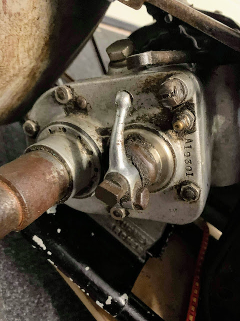
I'm not sure about this kickstart shaft - it looks much longer than any I've seen...


Both the Bowden-type clutch lever and the double air/ignition levers are missing.


I'm hoping to get this clean enough to use an adhesive repair.
The chain cover is also there, and will need a weld repair to one of it's feet.


It's also together, patinated and has some history. I've been in touch with the VMCC Central Scotland section to see what they know about this bike, since it comes from their patch and has hardly travelled.
So, how to approach it? In case you have forgotten, here it is:

So as you can see, it is pretty much original. All the bits you can see are period and most of them belong to this bike; the front mudguard is from the next generation - it is post 1930 and is the valenced front guard fitted to girder forked models after 1931, so it is in-period and may well have been with this machine for a long time. It is not, as I have written elsewhere, an example of the similar guard fitted to the front of my SQ4 - which is of course fitted with a telescopic fork.

So once again, like the W/NG, we have a patinated period bike with all original bits (matching numbers) and this one even has it's original registration - this is a real treat and has to be treated with respect. We will be following the 'repair and make safe' approach we did with the W/NG, collecting and repairing missing parts and where we have to refinish (heat damage from welding for example) we will attempt to do so while blending the original finish. We are very lucky in that the tank is in very good shape - but it also introduces a bit of a quandary, since the chrome tanks have a superb black finish lined gold & blue, with areas of chrome exposed, and this black finish really makes the bike look the dog's dangly bits. Here's a 1930 Model G, the top of the range, with the same tank:

So here's the plan. By and large, we will leave the finish as it is. I will repaint the tank panel, but attempt to age it and the lining to show that it is there and show some of it's former glory. I will replace the front guard with a D section guard of the correct size - the post 1930 guard looks superb on the later bikes but is not in keeping with the vintage look - but if someone turns up an old picture of this bike wearing that guard it may have to stay. I will buy that soon, get it painted and leave it to age for a year or two. I have the W/NG to model where the damage should be. There is also a fair bit of silver and purple paint on the rear guard, the chain cases and the rear number plate - if that can be cleaned up, so be it but those areas may need painting.
Other parts will be repaired, or replaced if they are completely missing. I plan to make parts that would have been plated from stainless, but fasteners will be blacked and painted carbon steel. Here's the detail:
Frame
To date, I haven't found any problems with the frame mainly because I haven't dismantled the bike yet. The paint is good, all the threads I have seen have been good, but looking at the saddle I suspect the saddle nose mount will be quite worn.The engine plates are all there, along with the footrest bar and one footrest. I have a spare one which needs repair but might do, but these are fairly easily available from Draganfly anyway. The footrest bar is bent but is just a bit of 7/16" round bar. I have the two engine plate covers around the dynamo, both of which need weld repairs.
The rear stand is completely missing - this will have to come from Ariel Klub Slovakia unless I can figure out how to make the legs or can miraculously find one...
Forks
The forks are complete and straight, but feel like they are quite worn - and these forks do not have bushes. The components, with the exception of the grease nipples are all there.

Tank
The petrol tank, cap and oil pressure gauge are all there and in nice condition. The cap needs a small repair internally; the tank has a few dents but little obvious rust and the chrome plating is intact. There are three of the original mounting bolts; I will make a fourth. Some of the mounting rubbers are there.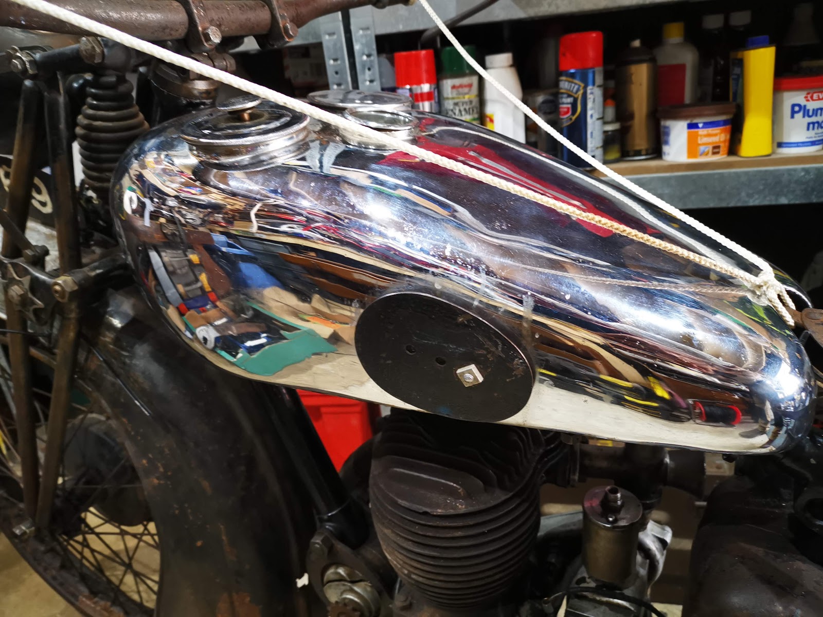
The knee rubbers and their plates are all there, though the rubbers are thoroughly squashed and are probably unusable.
The oil pressure gauge pipe and fuel tap are missing. I have acquired a suitable period tap with the correct adjustable corks from eBay:

It's a 1/4" BSP tap and will need an adapter - beggars can't be choosers.
Front Wheel & Brake
The front wheel needs truing and a spoke replacing. I'm hoping to get away without replacing the original rim, but that will require much closer inspection. The few spokes I have looked at appear sound and the nipples turn - I have dosed them all with Plus-Gas. The wheel turns freely and smoothly.The brake plate is there - the arm is there and it feels like the shoes are too. I have the brake rod and the torque arm but no adjuster or spring box.

Rear Wheel & Brake
The rear wheel runs true and turns freely, but it is missing at least two spokes. The sprocket, which is integral to the brake drum is worn and will need replacement; the brake plate, arm and shoes are there but the wheel spindle nuts are quite poor, one is missing a spacer and the other is seized on. The chain adjusters are both missing - I will probably source these from Acme Stainless, since the W/NG parts book, which includes both pre and post 1930 part numbering suggests they are identical to W/NG ones which are available.
Engine
The engine turns over - that is about all I know! It's lost a few fins, and one of the valve caps is broken but I guess that is patina. The timing chain case looks fine. There appears to be a weld repair to the base of the barrel but only an engine strip will reveal more:

Primary Transmission & Clutch; Final Drive
The chain & sprockets are there; the clutch looks complete apart from two missing springs and appears to lift when you operate the arm at the gearbox end.

I've seen much worse clutch drums than this:

There are several repairs on the primary chainguard like this, using rivets. The clutch dome is also split. I will probably weld up these riveted repairs as they are not adequately fixing the chainguard in place:

The rear chain guard is there and in good shape.
Gearbox
The gearbox appears to be complete apart from the kickstart spring and it's cover, and the kickstart lever cotter. The gearbox engages all three gears, but the hand change rod, one of it's clevises and some of the tank lever parts are missing. These are all parts that can be made on the lathe which is a good thing, as they are unlikely to be available anywhere.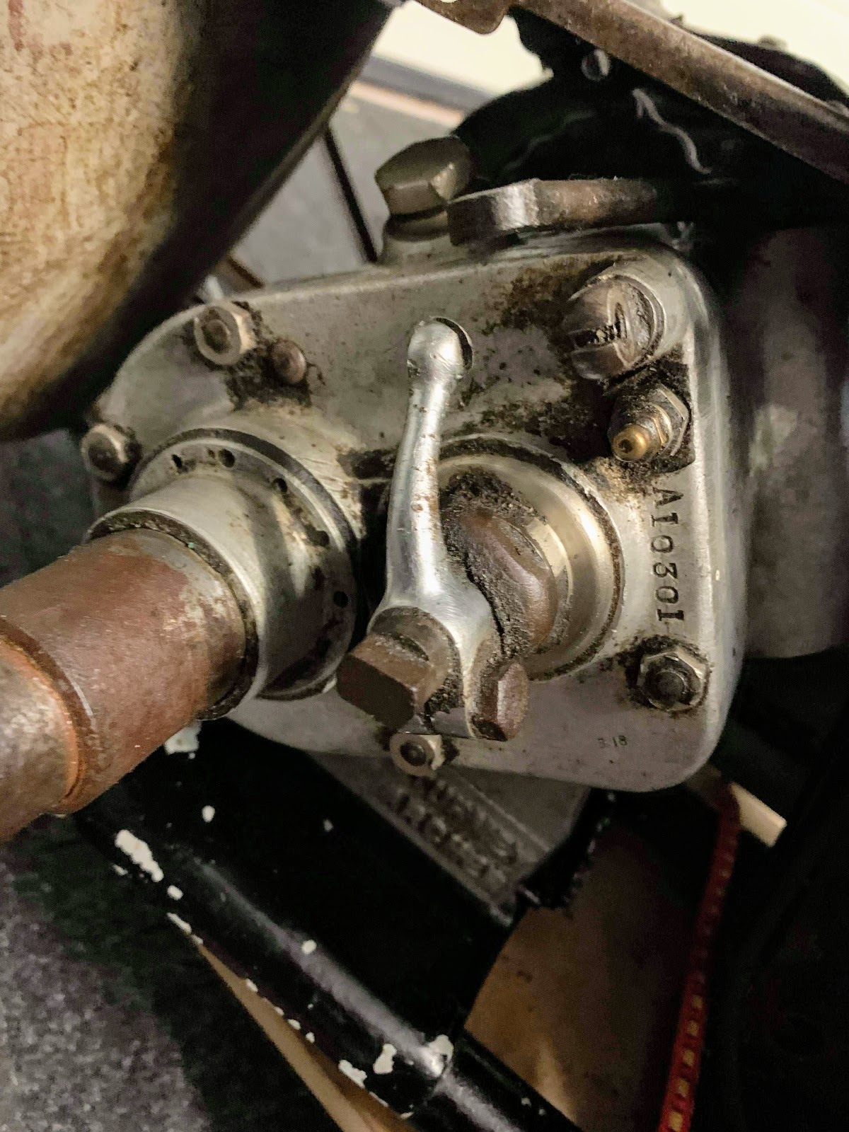
I'm not sure about this kickstart shaft - it looks much longer than any I've seen...

Carburetter
The carburetter is the correct Amal model 6, with the right float bowl - what sort of condition it is in is anyone's guess. I can feel the air and throttle slides.


There are no cables but I do have the remains of the fuel pipe.
Exhaust
The exhaust is there, the plating is poor but no worse than many. The fish tail is missing - I might make one from cold rolled carbon steel sheet or stainless, or I could buy one from the Ariel Klub Slovakia. The AA badge is missing from the silencer and the silencer bracket is bent; one or two of the clamps are missing:

Oil Tank & Lines
The oil tank is present, as are all the oil lines and unions. The tank cap is missing.Mudguards, Stays, Carrier and Number Plates
As I've discussed, the front mudguard and it's bridge are missing. I'll make the bridge using the W/NG one as a model but the guard will have to be replaced. The original number plate and it's mounts is there, the front stay is also there as is the front stand - the front stand is pretty rusty and will need surgery.
At the rear, both parts of the guard are there but there will be some welding to repair fatigue cracks. The carrier is there and in good shape, but all the fasteners are missing; the double mudguard stay for the detachable section is also missing, but I am told it is on the way from Scotland

Headlamp & Tail lamp
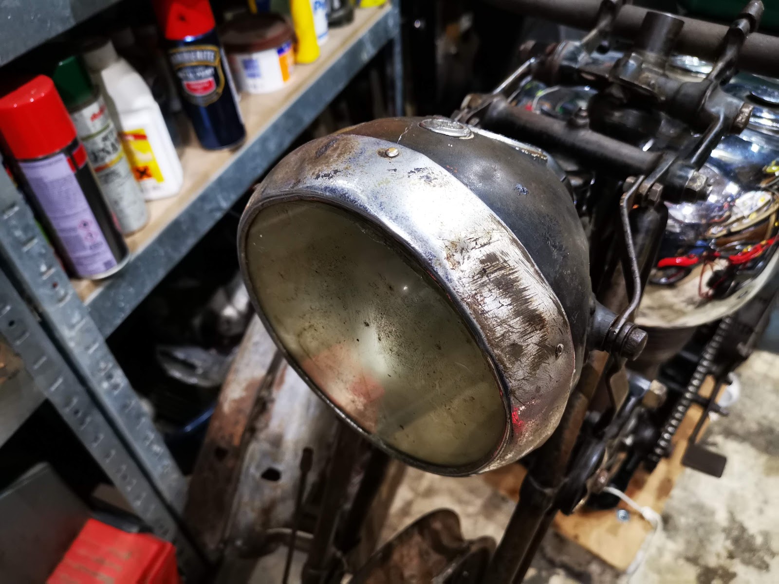
The Lucas H52 headlamp and MT110 tail lamp are both in place; the headlamp is quite battered. The plan is to dismantle both lamps and clean them; I will make a sandbag and knock the headlamp shell back into shape, hopefully the rim as well.

The rim is in particularly poor shape:

The H52 is very interesting - it has no internal wiring, just contacts:


I'm delighted these are all intact.


The rim is in particularly poor shape:
The H52 is very interesting - it has no internal wiring, just contacts:


I'm delighted these are all intact.


Handlebar and Controls
The handlebar, twist grip and both inverted levers are there. There is just enough plating on the bar to show it was once chromed. There are no handlebar rubbers, clips or cables.Both the Bowden-type clutch lever and the double air/ignition levers are missing.
Dynamo
The dynamo is the correct Lucas E3, and looks to be all complete though I believe part of it's clamp is missing. The drive end bracket has a large crack right across it.

I'm hoping to get this clean enough to use an adhesive repair.
The chain cover is also there, and will need a weld repair to one of it's feet.
Battery & Electrics
The battery tray and it's clamp are there, though the clamp will need a weld repair. There is the remains of the wiring harness attached to the headlamp which looks like it was rubber sheathed; the dip switch, horn button and horn are missing.
Magneto
The original Lucas KSA1 magneto has been replaced some time in the past with a BTH KC1, so this is probably a period repair or upgrade - the factory despatch record does not mention a non-standard magneto being ordered.
Saddle
The saddle is in place, with all it's springs and spacers - the nose bearing is pretty worn and the cover is missing. I'll make a new cover.


