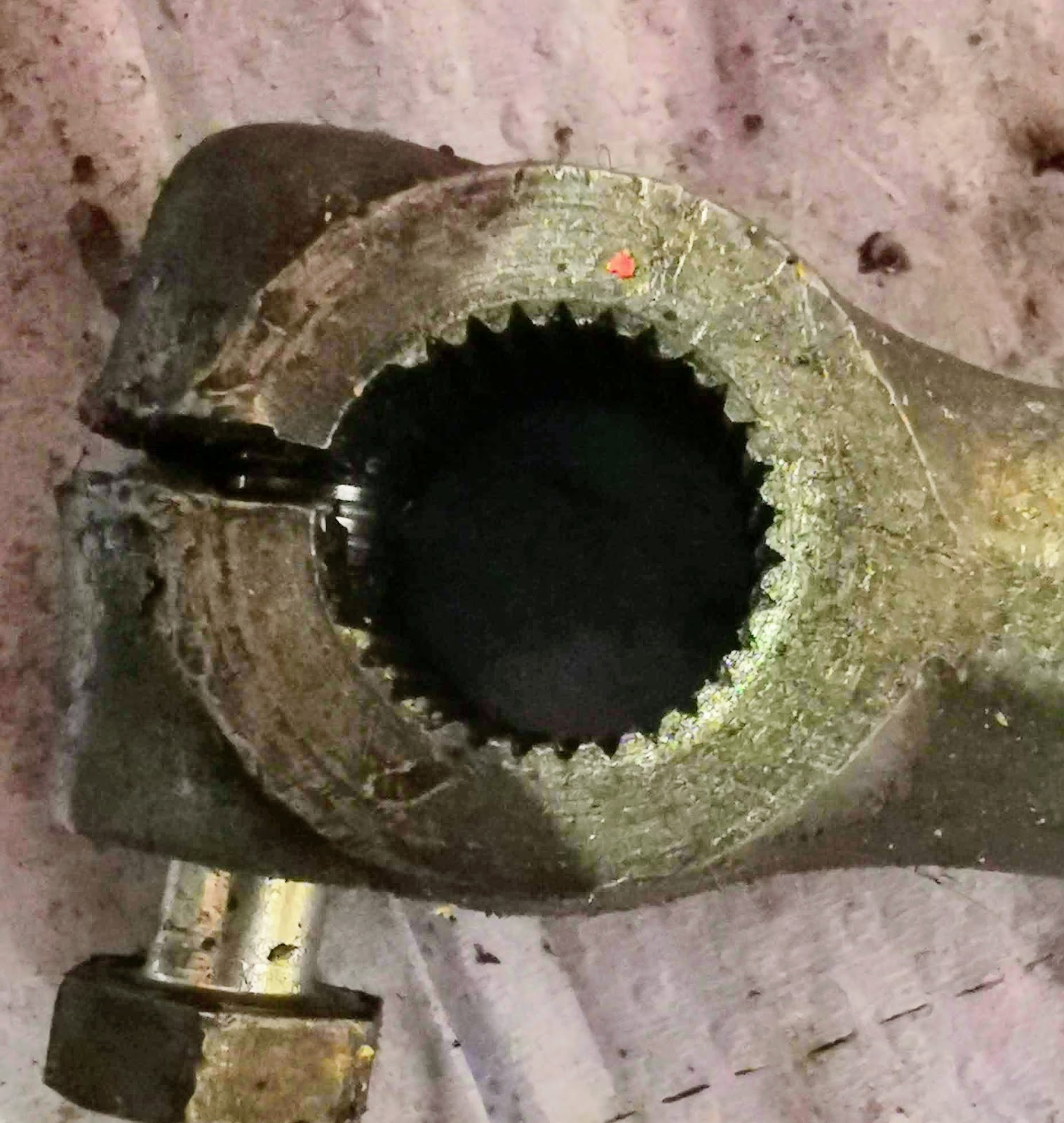
As you will have seen from my previous posts, I successfully built up the kickstart shaft from it's previous mangled stump and cut the splines on it only to find that I had misunderstood the spline pattern Honda had specified - in my defence, the kick start lever shows maybe 24 of the 31 splines the shaft needs; I had estimated 32. You can see the difficulty in the picture below:

I had another Honda kickstart shaft knocking about from a PC50 which fitted the QR50 lever beautifully. When I found it, (after I had cut the new one, by the way), I discovered that it had 31 serrations, rather than the 32 I had assumed. After a lot of research, I found a drawing which matches the PC50 sample perfectly:


What was much more of a problem was the fact that I had nothing to divide the shaft into 31 serrations - no 31 tooth gear, no 62 tooth gear and certainly no 93 tooth gear...
So, I'd have to make one. I took a chunk of aluminium I had knocking about and put it in the rotary table. Thirty-one divisions equates to 11.86° per division, which is not too difficult to resolve on the rotary table. I set up a small centre drill near the edge of this material, and drilled 31 holes around the edge, incrementing the rotary table by 11.86° each time:

That done, the next job is to move the three jaw chuck from the rotary table to the lathe spindle, trim the outside diameter and prepare the 12 mm centre bore.

Then the next job is to trim the outside diameter to start turning those holes into grooves. Really, the holes are only for angular positioning - they are not deep enough to provide the finished grooves and will be adjusted with a file later. The next time I do this however, I will run a drill through each hole while the work is still in the rotary table - that will save a lot of filing:

A little while later, we have the fledgling grooves exposed. The next job is to part off:

Of course it's not as easy as just parting off - I've extended the drilled holes using a hacksaw and needle files to form square-bottom slots the dividing pin will fit into neatly - we don't want it slipping out when we are trying to cut serrations.
I also dot-punched one of the slots so I could count them - I counted them several times to convince myself there was indeed 31. There was definitely 31, so I stamped the wheel to remind myself.
Next stop, prepare the shaft. This time, I managed to chip the carbide insert almost as soon as I laid it on the end of the shaft - carbide tips don't like intermittent loads, so I will use an HSS tool next time I try to machine an overlaid shaft.

This time, I am going to cut the splines in 0.125 mm (5 thou) passes to make sure the alignment is correct before going to full depth - full depth is about 0.9 mm. That saves straining hands and loading the machine, so the cuts should be more accurate. Here goes:

Part way through:

Almost finished now, but have a look at the crests of some of the splines. A couple of things happen when cutting these splines and I'm learning how to avoid the problems they cause:
Have a look at the spline at about 10 o'clock - there's a groove cut in the top of it:

So that's it. Finally, it fits; whether it will withstand a hefty boot is a tomorrow problem.


I had another Honda kickstart shaft knocking about from a PC50 which fitted the QR50 lever beautifully. When I found it, (after I had cut the new one, by the way), I discovered that it had 31 serrations, rather than the 32 I had assumed. After a lot of research, I found a drawing which matches the PC50 sample perfectly:

Building it up again was pretty straightforward.

What was much more of a problem was the fact that I had nothing to divide the shaft into 31 serrations - no 31 tooth gear, no 62 tooth gear and certainly no 93 tooth gear...
So, I'd have to make one. I took a chunk of aluminium I had knocking about and put it in the rotary table. Thirty-one divisions equates to 11.86° per division, which is not too difficult to resolve on the rotary table. I set up a small centre drill near the edge of this material, and drilled 31 holes around the edge, incrementing the rotary table by 11.86° each time:

That done, the next job is to move the three jaw chuck from the rotary table to the lathe spindle, trim the outside diameter and prepare the 12 mm centre bore.

Then the next job is to trim the outside diameter to start turning those holes into grooves. Really, the holes are only for angular positioning - they are not deep enough to provide the finished grooves and will be adjusted with a file later. The next time I do this however, I will run a drill through each hole while the work is still in the rotary table - that will save a lot of filing:

A little while later, we have the fledgling grooves exposed. The next job is to part off:

Of course it's not as easy as just parting off - I've extended the drilled holes using a hacksaw and needle files to form square-bottom slots the dividing pin will fit into neatly - we don't want it slipping out when we are trying to cut serrations.
I also dot-punched one of the slots so I could count them - I counted them several times to convince myself there was indeed 31. There was definitely 31, so I stamped the wheel to remind myself.
Next stop, prepare the shaft. This time, I managed to chip the carbide insert almost as soon as I laid it on the end of the shaft - carbide tips don't like intermittent loads, so I will use an HSS tool next time I try to machine an overlaid shaft.

This time, I am going to cut the splines in 0.125 mm (5 thou) passes to make sure the alignment is correct before going to full depth - full depth is about 0.9 mm. That saves straining hands and loading the machine, so the cuts should be more accurate. Here goes:

Part way through:

- the Honda splines run into a taper - they are blind, possibly because they are rolled in. The effect of this is that the tool comes to a dead stop which can potentially turn the toolpost, causing the tool to dig in or chip. Part way through this cut I turn an undercut for the tool to run into.
- If the tool chips, you have to remove it for a regrind, all well and good. The problem arises if you don't pay attention to the tool height. Now, when you are turning the tool height is fairly critical, less so if the work is relatively large but height is normally fixed by the adjuster on the toolpost. The thing is the QCTP typically does not repeat the tool height very accurately which is not normally a problem, but when you are cutting a serrated shaft the height of the tool has to be spot on to the height at which you took the last cut. If it isn't, the next cut won't land in the same place in the partially cut spline and will either cause it to be misshapen or could remove the spline altogether. So that's a lesson for next time.
- The reverse stroke of the tool has, I think, the potential to chip the tool. Shaping machines are fitted with a clapper box to allow the tool to disengage on the backstroke yet remain aligned on the forward stroke.
- The last thing is to do with the shape of the spline. I cut these splines with a tool ground to 60°, which makes 60° grooves between the splines. In a flat surface, 60° grooves would make 60° splines between them and the same would be true (to a lesser extent) on a shaft of very large radius. As the shaft diameter decreases, that same 60° produces a spline that increases beyond 60°. This is not too much of a problem, as long as you expect it - just grind the tool to suit.

So that's it. Finally, it fits; whether it will withstand a hefty boot is a tomorrow problem.