Due to my phased approach to building my SQ4, I put the forks back together without re-bushing them, many moons ago. They weren't too bad at the time and since Amelia had arrived in a number of boxes, and I had no Ariel experience at the time, I needed to get it assembled to understand what I was dealing with.
Dashing about Norfolk's roads last year showed re-bushing was going to be necessary this winter, so off we go.
The first step was to truss her up with a bungee to stop her shaking her head about. I planned to leave the yokes in place to avoid unnecessary disruption to a running bike.

Then, we need to get the front wheel off the ground without the ever-useful front stand. A scissor jack comes into play here:

Next step is to remove the front wheel, mudguard stays on one side and remove the fork top bolt and clamping cap screw in the bottom yoke. Next, we use the fork puller tool to knock the stanchion out of the taper in the top yoke:

With the leg out, we can start disassembling. We put the leg in the vice using the cast lug on the bottom - we don't want to clamp around the thin slider. Having lifted off the spring, we can use the special tool to remove the seal holder.

With the seal holder undone, we can think about the next step. Lift the seal holder about six inches up the fork leg, and tape it out of the way. Don't try and pull it off upwards, as the leg is tapered and you will stretch the seal.
The top bush retains the leg in the slider, since the bottom bush is bolted to the leg, and the top bush is retained by a circlip under the seal. Here's the circlip in place:
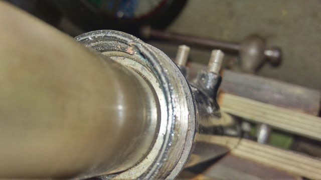
You can see, at just past 12 o'clock, a semicircular groove. This gives you access to the full diameter of the circlip. Get a small flat bladed screwdriver into the groove and push the circlip out. Find the end of the circlip and maneuver the screwdriver, still holding the circlip clear of the groove, towards the end of the circlip. When the end of the circlip is free of its groove, get a scriber or another small screwdriver under the end of the circlip and maneuver it upwards, moving back along the circlip as you winkle it out.
You can then pull the leg out of the slider:

These two pairs oil holes ( the others are behind the leg) show this is a post 1953 leg, which gives more progressive rebound damping than the earlier legs (which only have one pair of holes). The long top bushes which go with these later legs are shown in the picture above; earlier legs use a top bush of about half this length.

Here are the new bushes in place.They were both oversize on the outside diameter and required some 'easing'; The lower bush is retained by the stanchion bottom nut.

The next job is to lubricate the buses with some SAE 30 and place the stanchion back in the slider. You can then maneuver the circlip back into place by aligning one end in it's groove, and pushing the clip away from the retained end with a small screwdriver until it snaps into place. Next, put a little more oil around the top bush and screw the seal holder back down with the factory tool; fit the spring and you are done:

This is a new H18-48 stanchion top adapter, courtesy of Mr. John Budgen. The previous one succumbed to an unfortunate incident involving a copper mallet and a lack of forethought. You can see how it used to look in the previous picture - they are not very strong and cannot tolerate much abuse.

Once you have it all back together, you will need to fill the forks up with some SAE 30 engine oil. This is simply accomplished by removing the top bolt and, with a small funnel, pouring sufficient oil into the leg such that the level is 17-18 inches (43 cm) from the top of the yoke.

Dashing about Norfolk's roads last year showed re-bushing was going to be necessary this winter, so off we go.
The first step was to truss her up with a bungee to stop her shaking her head about. I planned to leave the yokes in place to avoid unnecessary disruption to a running bike.

Then, we need to get the front wheel off the ground without the ever-useful front stand. A scissor jack comes into play here:

Next step is to remove the front wheel, mudguard stays on one side and remove the fork top bolt and clamping cap screw in the bottom yoke. Next, we use the fork puller tool to knock the stanchion out of the taper in the top yoke:

With the leg out, we can start disassembling. We put the leg in the vice using the cast lug on the bottom - we don't want to clamp around the thin slider. Having lifted off the spring, we can use the special tool to remove the seal holder.

With the seal holder undone, we can think about the next step. Lift the seal holder about six inches up the fork leg, and tape it out of the way. Don't try and pull it off upwards, as the leg is tapered and you will stretch the seal.
The top bush retains the leg in the slider, since the bottom bush is bolted to the leg, and the top bush is retained by a circlip under the seal. Here's the circlip in place:

You can see, at just past 12 o'clock, a semicircular groove. This gives you access to the full diameter of the circlip. Get a small flat bladed screwdriver into the groove and push the circlip out. Find the end of the circlip and maneuver the screwdriver, still holding the circlip clear of the groove, towards the end of the circlip. When the end of the circlip is free of its groove, get a scriber or another small screwdriver under the end of the circlip and maneuver it upwards, moving back along the circlip as you winkle it out.
You can then pull the leg out of the slider:

These two pairs oil holes ( the others are behind the leg) show this is a post 1953 leg, which gives more progressive rebound damping than the earlier legs (which only have one pair of holes). The long top bushes which go with these later legs are shown in the picture above; earlier legs use a top bush of about half this length.

Here are the new bushes in place.They were both oversize on the outside diameter and required some 'easing'; The lower bush is retained by the stanchion bottom nut.

The next job is to lubricate the buses with some SAE 30 and place the stanchion back in the slider. You can then maneuver the circlip back into place by aligning one end in it's groove, and pushing the clip away from the retained end with a small screwdriver until it snaps into place. Next, put a little more oil around the top bush and screw the seal holder back down with the factory tool; fit the spring and you are done:

This is a new H18-48 stanchion top adapter, courtesy of Mr. John Budgen. The previous one succumbed to an unfortunate incident involving a copper mallet and a lack of forethought. You can see how it used to look in the previous picture - they are not very strong and cannot tolerate much abuse.

Once you have it all back together, you will need to fill the forks up with some SAE 30 engine oil. This is simply accomplished by removing the top bolt and, with a small funnel, pouring sufficient oil into the leg such that the level is 17-18 inches (43 cm) from the top of the yoke.

For reference, here is a sectioned drawing of the fork from Mr Charles Weller's book.