Showing posts with label drill. Show all posts

Saturday, 14 March 2026

Model A - this is getting boring

 While we wait for the long series drills with which we can finally fit the kickstart pawl, we can look at preparing to drill out for the layshaft bush and for the relief drilling that will clear the layshaft first gear pinion. I need to do some measuring to ensure I understand the various dimensions that will be required, but I know that the bore to clear the pinion will be in the region of 1" diameter.

You will recall that in a previous post we machined off the flange that had been used to hold the shaft in the rotary table, reducing it until it would pass through the fixed steady. We see it in use in the picture below during setup:


The short 5 mm hole that has been used for the revolving centre is opened out progressively until we run out of twist drills. This is the 10 mm drill passing right through and into the body of the shaft:


And here it is opened out to 7/8", which is the largest drill I possess - it actually has an MT2 taper and fits directly in the tailstock:


The next job is to part off the stub, but sometimes it is easier to rethink your approach to a job. I set the lathe up to part off this stub after I moved the fixed steady to the 1 1/8" section, but actually I realised it would be much easier to saw it off:

That took less time than setting up. The orange dust is from the saw blade!

This rudimentary sketch shows us what the dimensions of the hole need to accommodate. As I have no wish to bore the hole to over 1" all the way into the shaft, reducing the wall thickness just where it needs to be strongest, I will make a stepped bush to accept the layshaft and provide a thrust face for the low gear pinion. This will be 1" or thereabouts at the inboard end, and reduce to 7/8" for most of it's length. This will give a thin wall over most of the length of the bush since the shaft is about 11/16".


That's the bore done for the low gear pinion - it's 1.010".


I used a depth micrometre to determine the dimensions of this hole - it's a nice tool that I bought from someone at the railway a few years ago:


The whole has two diameters - one for the layshaft and one for the low gear pinion. Both of these diameters will be bushed:


The larger of the two fits the low gear pinion beautifully:


The smaller one clearly fits over the layshaft:


We can also see that the length of the 1 1/8" section is just right:


Now we need the bush, but before we make that the package from Tracy Tools has arrived with the long series drills we need to fit the kickstart pawl and it's pin but before we do that we'll spend the day driving one of these:

Saturday, 12 October 2019

Rad & Tacho

It's a well established fact that Honda screws of the 1970's are made of Cheddar with a thin coating of Stilton, and these radiator cowling screws, which face into the weather are no exception.


Fortunately cheese is no match for High Speed Steel and the heads are soon removed.


The radiator cover comes off easily after I have drilled the heads off all but one of the screws.


This exposes the radiator, which is in fine shape and will just need a clean and a repaint. I will run a tap through those rusty screw holes:


Handy use for that cat-litter tray:


Anyone involved in vehicle restoration will understand the presence of the bolt cutters I'm sure. In this case, they made short work of one of the hose clamp screws, allowing me to release the clamp without destroying the wire part


With the radiator off, we can see the fan.


Now the method usually recommended for removing the fan is to push it off with an M14 x 1.5 thread, which, the forums tell me helpfully exists in the front wheel spindle:

Honda CX500 Fan Removal

Of course, what the forums fail to mention is that the nose of the wheel spindle is slightly tapered, and when you screw that into the fan boss the threads are not engage to full depth. Then, when you put some force on the spindle, the aluminium boss threads strip!

Honda CX500 Fan Boss

Idiot, should have checked. Now we will attempt to re-cut the thread and use a better quality puller - if not, 9/16 UNC may be an option.

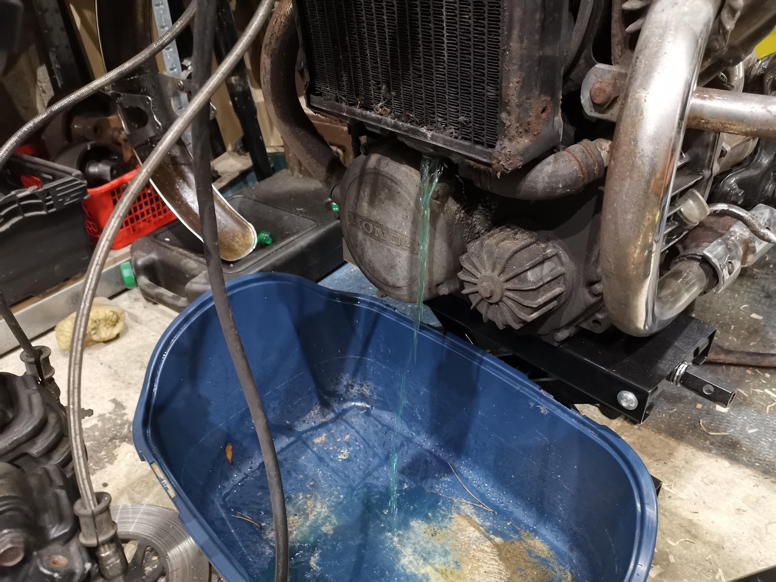
The four engine mounts are used to retain both the fan shroud and the crash bars. The CX looks better without it's crash bars doesn't it:


Much slimmer:


The fan shroud is full of oily muck. I suspect the cam nose oil seal has had it:


Fortunately, there is enough thread in the fan to allow to be removed with an M14 x 1.5 screw:


And more oily muck. The camshaft nose looks wet:


To get the camshaft holder off, I want to relieve as much spring pressure on the cams as I can. So, with one side set to TDC and the valve clearance adjusters backed off on the other side, I can pull the holder off more easily.


Having discovered that the non-functioning tacho was not down to a faulty cable and that the drive spade was not turning, I hoped to find the tacho drive shaft broken or the driven gear stripped.

Unfortunately, it was not to be and I found the drive worm on the camshaft had lost all its teeth.


The only way to fix this is by changing the camshaft. Longer term, I will fix this and I will start looking for a new camshaft. For now, since I know the cam chain does not yet need replacing, I will put it all back together safe in the knowledge that I have freed all the rusted nuts and can pull it apart again quickly. I don't have the bench space to tackle this now. If it transpires that the starter clutch is dodgy - its quite rattly - or the camchain wears out, or the stator fails, then I will pull it apart but since all I have is an instrument failure - hardly mission critical - then it stays together for the foreseeable future.

Friday, 22 August 2014

Oil Pressure

So as I have mentioned previously, my plan was to spin the engine up on the big power drill. I've now done this using a 1/2" square driver with a hexagonal shank in the drill chuck, with the drill set to 2nd gear - slow speed, high torque. The drill drives the engine through the crankshaft nut under the oil pump.


I connected a short hose to trap any fluids coming out of the oil pressure gauge line and take them back to the oil tank. Because of course the timing cover is off, there is a lot of oil in the drip tray which comes from the rear main bearing. 

The plugs are out to reduce the torque required from the drill.


And here it is:

Evidence of oil emerging from the return line. When the drill is running, you can see this pouring out, and you can see it at all eight rockers as well. Its noticeable that the inlet rockers get a lot more oil than the exhaust rockers - Ariel should have adjusted the size of the oil holes (smaller in the inlet rockers) to increase the feed to the exhaust rockers.

After a few minutes on the power drill, the bike is noticeably easier to kick over. Next I refitted the rocker cover studs and I put the tank and the oil pressure gauge back on and ran the test again looking for measurable oil pressure.

At maybe 250 rpm on the drill I am getting something like 25 psi.