You might remember from the recent girder fork investigation post that we had a lot of movement in the forks - in fact a 3/8 inch variation in wheelbase. It was obvious that a lot of this was down to wear in the links and wear in the spindles.
I contemplated reworking the original links for a while but while chatting to the AOMCC Black Ariel spares specialist I discovered that reproduction links were available from the club at a good price, so bought a set. They're not perfect - for example the middle links are smaller in diameter than the originals so I will keep the originals and repair them at some point.
For some reason the top links on the 1929 and 1930 bikes are not fully threaded:
The club spares officer also recommended I bought a new spring. It's certainly true that old fork springs I've used in the past have been very soft and looking at the old spring previously it was clearly a bit stretched. Again new ones are available at a reasonable price:
Putting these bits together with the old spindles revealed a significant reduction in play.
A few days later, the new spindles arrived from Acme Stainless - and very nice they are too. On bikes of this era, you don't need the knurled washers - these arrived in 1934. I bought a pair of headstock nuts as well since I was one missing and pulled up the steering head bearings a bit more.
Putting all these in place removed all of the play in the forks. I now cannot detect any variation in wheelbase.
Stuck in the steering column there is the beginning of the blanking plug that is used on the Model A which was not supplied with a steering damper.
That plug will be chrome plated eventually. I'll finish it machining it long before that happens!
I guess that I have been shying away from looking at the girder forks for a while - it occurred to me that I have never dismantled a set of forks like these but having dived straight into it, it's dead easy.
The first job was to make sure the back of the bike was strapped tightly to the lift table and then use the scissor lift to raise the engine a bit. Then I gingerly loosened the front wheel in its clamp and confirmed that everything was stable.
Pulling the forks about revealed a lot of movement and I made a little video:
There you go - clearly a number of problems there.
Removing the spindles and replacing them with scrap round bar allowed me to have a look at the links. The part you would call the bottom yoke in a conventional telescopic fork is called the fork crown by Ariel, and the links attached to the crown at the bottom are pretty worn:
Both sides, as you can see. This means the links will need bushing or replacement; the top ones are worse.
Fortunately removing the crown and steering column revealed that indeed there were no balls in the steering head bearings, so that will account for a lot of the movement.
I will probably clean up this area and leave it in factory paint as it is in quite good condition.
The steering head races had two balls left in them. We will clean them up and see how worn they are.
Ariel call this bit the ball head clip - it carries the handlebars and the spindle for the top links. Said spindle was absolutely solid in the clip and I had to resort to the splendid Rothenberger Surefire 2 to warm the grease up and get it to move.
The spindle came out eventually - but look at the state of it. The bike has also been used with the spindles loose which has worn most of the thread away and part of the link too.
The main girder assembly looks pretty good:.
I'll repair these worn areas though - it looks like the mudguard has been loose and has fretted the fork leg. These will build up with weld.
Whilst the girder fork assembly is still a bit contaminated with old grease, I'm quite confident that the spindle bores are good enough.
I spent a while getting all cleaned off the next afternoon. The two races that fit into the frame are chipped but with new balls seem to work ok.
I'm going to replace the spring while I can. You remove these by tapping the end with a hammer and a punch to unwind them from their fixing spiral:
This is the lower fixing - the upper one is part of the main girder.
You can see that the spring has opened up - it must be quite soft.
I rebuilt the forks with the new balls in the steering head to determine how much play I had solely coming from wear in the links and spindles. With these old parts in place, the wheelbase varied 3/8".
I've been in discussion with the Black Ariel spares man for the AOMCC and have some new parts on the way.
Out and about on the Huntmaster again today shows that the steering head bearings are getting sorted. The handling is as good as ever, maybe a bit more sure on its feet and braking is very smooth - there is much less judder from the front forks - though it does need a little more adjustment.
Yesterday I checked the contact points and found in both positions that there was a dragging fit on a 12 thou feeler gauge. The bike started readily as usual this morning and ran very well on a 4 mile trip to Cromer.
There is conspicuous oil in the drive side silencer however I didn't notice any smoke. Is this a temporary problem that comes from leaning the bike over and dripping oil into one of the valve guides? Certainly it happens after parking on the side stand and of course the side stand causes the bike to lean towards the drive side. The oil in the exhaust could have come from the various smoke experiences I've had over the last few days. Am I clutching at straws? Is it just the rings bedding in?
The handlebar mirror is a little bit loose and needs nipping up, and the centre stand needs some oil on the pivots. Oh, and before I go, the gear lever needs to come up a notch!
Changing or replacing the fork oil on these later Ariels should be a breeze with their neat drain plugs and filler caps and I was approaching this job with all the confidence of the naïve...
The stainless filler caps came (I think) from Acme and need a bit of a polish - I have given this a few minutes on a 150 grit wheel and you can still see some machining marks, so we will need something more aggressive. These are 1/2" CEI and fit with a fibre washer underneath:
For some reason that I don't currently understand, there is a further 1/2" CEI plug underneath these top screws, which closes onto a seat on the fork top nut, leaving a hole of around 1/4" diameter:
This plug is very short - it's easiest to lift it out with a magnet on a stick:
You need 7.5 fl oz of SAE 30 fork oil for each leg - that's about 215 cc. Fork oil is designed to avoid foaming and to protect the inside of the sliders and stanchions from corrosion. I'm going to use the 250 cc syringe that I use for gearbox filling for this job.
Should take seconds.
Here we go. One good push will have it done.
Or not. It's cold, the oil is thick. The hole is small and the oil ends up on the lift table.
I'll stick a tiny tube into the hole to let the air out...
That works, but it takes a ridiculous amount of time.
Contemplating a special nozzle or a tin funnel, I spent a while gazing around the workshop looking for inspiration which I found in the drawer of goop tubes - silicone sealant, caulk, no more nails (other glues are available) and other stuff like that. This is part of a decorators caulk cartridge - the nozzle is long and thin enough to go right through the top nut of the fork stanchion, so the oil is introduced to the full bore of the stanchion and is already past the restriction.
Of course, there is precious little room for the air to come out, but it does, slowly. You have to fill the funnel twice to get all the oil in, but at least you can sit down and pick your nose while it dribbles in.
It looks like a detail, maybe even a sign of obsession, but choosing the right thread is actually really important.
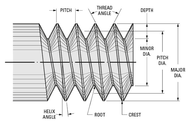
I've been working on the forks this week - you may have noticed - and one of the bolts I removed was conspicuously coarse - it was a 3/8" BSW bolt, 1 3/4" long: the front wheel spindle clamp bolt. British Standard Whitworth threads are coarse (20 threads per inch) and consequently strong for their size. What they are not good at is staying tight when subject to vibration. You use them in alloy, but you will find that virtually all the other threads on a bike of this vintage are British Standard Cycle, which in this size is 26 threads per inch. The helix angle in a 26 tpi thread is much smaller than that in a 20 tpi thread, and consequently the thread is much less likely to work loose under vibration.
It also pays to choose the right length - this application needs a 1 1/2" bolt, so that most of the threads are hidden in the nut and don't get filled up with debris from the road.
These are just 2BA cheese head screws cut down to about 1/4" and provided with fibre washers:
To give them a better chance of retaining some fork oil, I've loaded them with Loctite 577 thread sealant.
The other thing that I need to remember is that I need to find 7.5 fl oz of SAE 30 oil to put in each fork leg.
Also in the news today - the right hand tank knee rubber is now on, I've tightened some more bolts and I've scraped enough paint off to allow the petrol tank cap to fit.
Lots and lots of little jobs today. I've put the front wheel back together and back in the bike, noticing that the centre stand is off the deck when the front wheel is high enough to come out - I used the scissor lift to get the bike high enough; that centre stand is going to have to come off again.
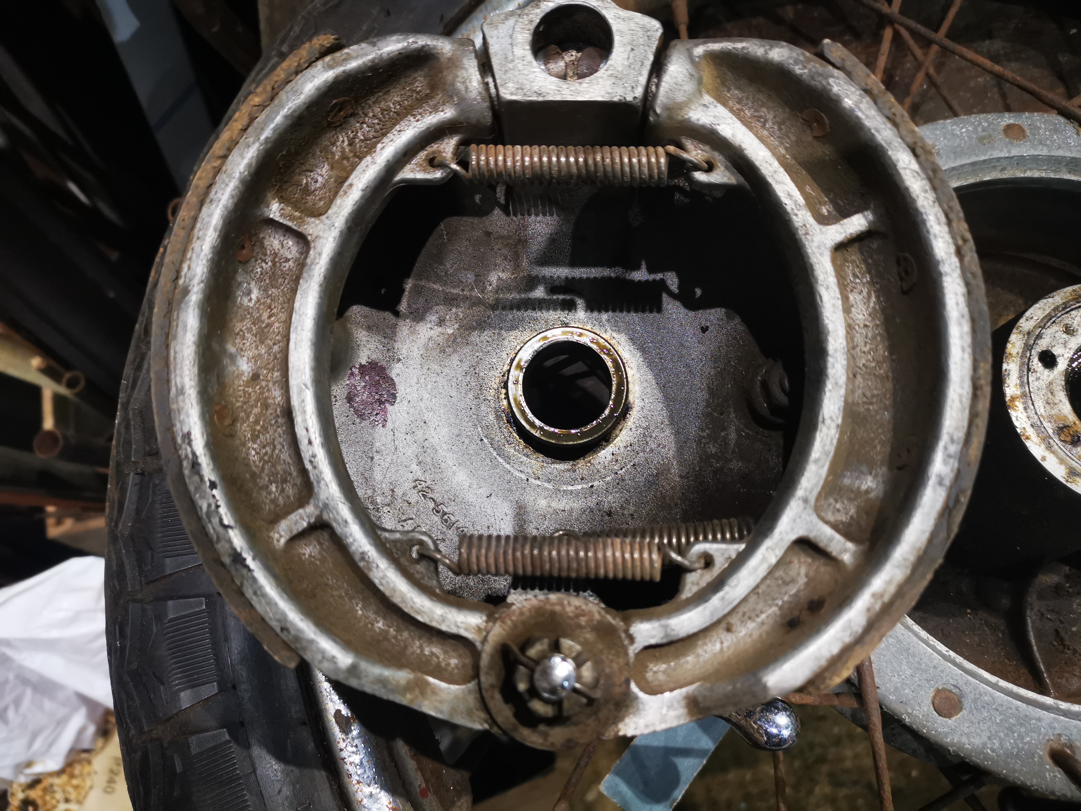
Moving on to the front brake, it's time to unearth the mysteries of the full width hub. This is the view from the parts book:
It looks like the brass bearing retainer used in the half width hub is still there but now has a sheet steel ring riveted to it retaining a small felt grease seal. This one has been a bit butchered and the steel ring is loose:
The one on the other side is still in place. That tube passes through the bearing and acts as a centralising mount for the brake plate:
As might be expected, there's a thin coating of rust on the drum, easily cleaned with various abrasive papers.
This spacer fits over the tube in the previous picture, between the brake plate and the fork leg. It was stuck in the fork leg - I guess there is some paint to clean out.
Both the shoes are glazed. This is the trailing shoe:
This is the leading shoe, though there is no lead-in chamfer:
As we found at the rear, the parts are all present and in good shape - but no lead in chamfer:
As an aide-memoire, while I clear out the paint from the front axle clamp in the fork leg, note that the drain plug is missing and there is obviously no oil to damp the fork movement!
Next job is to add a lead-in chamfer to both shoes and to reassemble & retest. After that it's:
Fit the tank knee rubbers and aluminium trims
Fit the tank, not forgetting to soak the fuel tap first
Sort out the wiring routing under the dashboard and find the dashboard fixing screws
Replace the rims and spokes when the tyres turn up.
After three years in the field, the little beast is back. The boys are complaining the bike has no power after ten minutes running and with busy lives, my son and daughter in law have no time to check it out - so it’s back to Grandad’s workshop.
The Square Four is now off the bench to test the kickstart against the clutch, and then close up the clutch, refit the exhaust and test ride it. All went well with that, so the QR can go on the bench:
The first thing to attend to, and rather alarming, is the fact that the fork top threaded inserts are both loose. Now, these had a ring machined into them which allowed them to sit in the top of the fork leg, which I welded into the fork leg. Now, there is no evidence that the ring was anything other than an interference fit around the insert - indeed, there is no evidence that the insert was anything other than an interference fit in the fork leg.
Now, the inserts are retained in the fork leg by two strong plug welds on each side of the leg:
Next job, the tank. The wrap hasn't survived very well on the tank - the shape is small and complicated. I've pulled it off and treated it with some special plastic primer:
The primer is actually clear - ignore the grey bit, that was an experiment with the ordinary PlastiKote primer to test adhesion: it doesn't work very well, but the special stuff is excellent. This RS Paints Honda Helios Red doesn't come off:
The lack of power appears to be down to the choke - the choke cable goes into the carburetter through a plastic nut which has broken, allowing the choke cable to come out. When it comes out, it appears to operate the choke such that the mixture is rich all the time, even with the choke knob pushed in. That will certainly lead to a lack of power.
The part of the nut that was broken retains the boot, which in turn retains an elbow and the cable.
I turned a new part up from brass and pressed it into the old nut, which I had bored to suit. It starts very well:
As you can see at the end of the video, it dies if you fully open the throttle - the kids were complaining that it didn't have much power. The float height is bang on:
It appears after a lot of searching and cross checking Honda part numbers that a Keihin PA26 carburetter with a #78 main jet is correct for all years of QR50 production. This is the main jet out of mine, which is marked PA 28D but still has the 12.2 mm throat of the correct carburettor:
A #58 is not a #78! It looks like it gets very weak at full throttle, something born out by the colour of the plug. I've made a new carburettor spacer while I wait for the new jet:
A few days later, the new jet arrives as expected - but it's the wrong size. Some of these little carbs use a jet with an M7 x 0.75 mm thread, and these are available; unfortunately mine uses an M6 x 0.75 mm thread and these are not available. So what I did was measure the diameter of the new #78 jet using a range of small drills - I found that a 0.8 mm would not go in, but a 0.75 mm would; the #58 would accept a 0.55 mm, but not a 0.6 mm. I concluded these Keihin jets are identified by their diameter.
One option would be to put the new jet in the lathe and reduce the diameter, and I probably would have gone down this path had I possessed a M6 x 0.75 mm die (it's a fine pitch) but I didn't fancy buying a die or setting up for single point threading, so I did something that ideally you should never do and drilled the old #58 jet out to 0.75 mm, which might leave it a bit lean.
It doesn't run out of breath at high rpm any more: