Showing posts with label bullet. Show all posts

Wednesday, 15 April 2020

QR50 - Generator Stator

Updated: first published March 2020

While we are in lockdown to slow the spread of Coronavirus, I have started to look at the QR50 electrics. It's pretty easy to solder up a new wiring harness in the office.

I'll write about the wiring harness in another post but first, before we start on that we need the stator casting repaired. You might recall I mentioned that it was toast and that I had bought a PA50 stator (complete) to replace it but that the PA50 stator does not fit...


Pictured here is the original stator, with all the wiring missing and the CDI sensor coil burnt out somehow. Fortunately the exciter coil is continuous, because the PA50 coil is bigger; the PA50 trigger coil however is identical to this one and will just swap out.


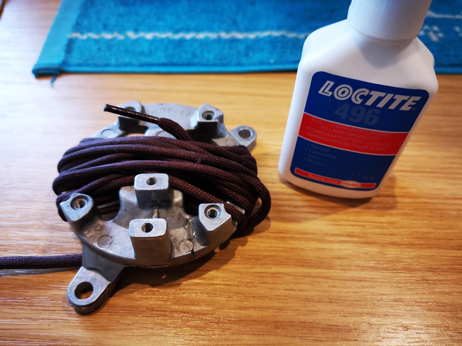
This is the back view. If you look closely at about 10 o'clock, you can see a crack in the casting. I did a little research on the Henkel website for a suitable cyanoacrylate that had low viscosity to wick into the crack and came up with Loctite 496, as a low viscosity adhesive specifically formulated for metals. Unfortunately the high temperature alternative, 4203, doesn't seem to be available anywhere so we will have to see how this goes.


Here's the crack, bound up with a bootlace...


And as if by magic, I now have a rebuilt stator. I've reused the existing exciter coil, which has just been gently cleaned. The trigger coil comes from the donor PA50 stator, and the wiring has been replaced:


Inboard view:


And here's the stator trial fitted in the offside crank case:


Monday, 28 July 2014

Dynamo & Split Bullets

Time to hook up the dynamo. The split bullets so beloved of Mr Lucas are a crude but effective design. I thought I'd show you how to use them. These came from Feked, though you can get them all over the place.

Strip the cable insulation so that there is a similar length of bare wire as the length of the bullet:


Push the wire into the wider end of the bullet, and fan the wire evenly over the bullet:


You may need to pass one of the wires through the Tufnol retaining piece before you fit the bullet. Push both the bullets into their socket in the dynamo and screw the retaining piece in place firmly. You will see the bullets slide into their slots:


Then you are done. Fit the dynamo end cover, making sure you don't trap the flexible brush wires in it, and screw the cap down:


Wednesday, 16 April 2014

Wiring Up

While waiting for head studs, I have the tank off, some spare time and some wire...

I can make the wiring harness. I have the old harness, which conveniently shows me how the various branches broke out of the rubber tubing to go under the tank and off to the dip switch, horn push and other places. It also shows me how it was constructed:


So, having fitted the old harness back on the bike, we can construct the new one around it.


I'm using rubber covered wire, as was originally used, obtained from a solar-panel supplier. It's a lot less shiny than the PVC coated wire we get now, but I'm not wholly satisfied - it is not as black as the original wire. I'll use some cheap tie wraps to keep it bundled together until I am ready to put the sleeving on:


You might recall that I made a wiring diagram, and we will use that to build up the new harness. I start by fitting some of the components so that I can lay in enough wire to reach them, like the dynamo and the ignition switch.


Then we lay in the wires, one by one, using loose tie wraps along the frame, handlebars and mudguard stays:


I'm using clear spiral wrap to hold the harness together for now, until I have finished laying it all out. I know from experience that it's better to work with this temporary arrangement until you have all the wires in and marked. There is always something to add or re-route, or lengthen!

These little uninsulated bootlace ferrules are very useful for tidying up areas like the ignition switch, horn and lighting switch, where the terminal is designed to clamp bare wire:

Sunday, 3 February 2013

Wiring, or Muck & Bullets

Regular readers will note that this post was originally published a few days ago. It's been moved to it's own page since it is growing...

Moved by a discussion on cable ties on the AOMCC forum (how many rivets in a BR Standard Class 5?),  I started to look closely at the wiring harness.

It is a curious thing indeed. Whilst it has been modified, there are many original cables left in it. These are rubber covered, used 14 plated 0.030" strands (that's 1.0 mm2) and use small coloured bands at each end to determine the cable colour - insulation is always black. The diameter is equivalent to a modern 2mm2 or 3mm2 standard PVC cable (not thinwall), which I may use when rebuilding.

I've discovered that you can buy single cored HO7 (rubber covered, oil resistant) cable, but getting it in the right size and the right colour is a problem. Since it is specified for trailing mains cable, for frequent handling it tends to be in 3 core brown/blue/green & yellow for single phase mains supply.

We shall persevere with the help of Mr. Google. I might ask this chap http://www.vintagemotorspares.com/ who looks he has some useful stuff and is local to boot. Or the 318TQ cable here might do it too.

Connections are made with conventional bullets, with the rubber covered single & double snap connectors. My bullets are solder type as shown in the picture, not crimped:

The real curious thing is the sleeving. There is a short (maybe 1 foot) length passing from the front under-tank area to the headlamp; another, smaller diameter from the headlamp to the dip switch; a bare single strand is provided for the horn push. It appears that from under the tank the wires passing to the regulator/coil battery are uncovered. There is a small (1 inch) length of rubber sleeving tying together the wires that start and finish in this area (dynamo to regulator for example) - and that is it! no more sleeving. I suspect that the wire to the rear light was a single strand, since in 1951 there would have been no stop switch. My harness is pretty mangled in this area.

It must have appeared a bit of a dog's breakfast, with all that loose cable!

There is a wealth of information on the AOMCC forum about cable fastening, HERE. However, here is a picture of my rear mudguard:

Now I know that most normal people will glimpse that picture and instantly lose interest, and those that pause for thought will then wonder why we bother with this obsession of ours, but for those of you that want to know how Ariel retained the cable to the rear lamp inside the rear mudguard, well, here is the picture you have been searching for all those years.

There are about five of these little tags welded around the LHS (horn/battery side) of the rear mudguard, and the cable slots behind them. You bend them a little bit to retain the cable.
Note that my mudguard is of the one-piece variety, that pivots around the forward bolts (the ones that pass through the seat lug).