Updated - first published February 2014
This is the section where we deal with those cables that you oil regularly, that operate your clutch and your front brake. They are an important part of your biking experience, not only for your safety but also to make the experience a pleasant one – there something rather magical about you & your bike cruising smoothly along a sunny lane, with everything operating as it should. One of your main connections to your bike is through those control cables:
Cables & Uses
Since the dawn of the bicycling era we have had the Bowden flexible cable. Your typical old motorcycle will have several – for the front brake, the clutch, the throttle – and maybe for the back brake, an air slide, a decompressor and the magneto as well.
You may have noticed that these cables are not identical – in fact there is a whole variety of components used in control cables throughout the biking world. Like many other facets of life, cables have their own jargon. Here are the keywords:
You might recognise this as something like a Bantam clutch cable – though Bantams have the adjuster mid-way along the length of cable, not at one end.
Cables are manufactured from multiple strands of high-tensile steel wire, formed into a cable (i.e. twisted together in contra-rotating layers) provided with a compression resistant outer casing formed as a spiral of rectangular section wire, covered in a PVC or cloth sheath. The outer is finished with a pair of ferrules at each end, to protect the ends, and the inner is fitted with a pair of nipples, usually brass, to allow the handlebar lever or twist grip to pass the load into the cable, and the cable to transmit that force into the clutch, brake, or throttle slide.
Talking about loads, of course we realise that the load passed into a throttle slide is far less than the load that is required to bring a heavy bike to a stop with the front brake. So, we need several different cable sizes to cope with these loads – we don’t want to operate the tiny throttle of a BSA Bantam with a cable suitable for the rear brake of heavy bike like a BSA A10, because it would be way too stiff and the friction alone would probably stop the throttle closing.
So there are several cable sizes in use:
It’s useful to note, when you are buying cable components that several of those inner wire diameters are similar – 0.062” is not so very different from 0.075”, so be careful when measuring!
When you have bought your inner wire, store it carefully. One of the key elements of successful soldering is cleanliness - solder will not 'take' to greasy wire or to wire that has been out in the weather for a while. The inner cable should be free of grease and the plated wires should be shiny - dull corroded wires may not solder at all.
Outer Casings, Nipples, ferrules, inners etc.
So, to help you decide which components you need, here are some tables identifying the various parts:
Inner Cables & Ferrules
Here are the dimensions for the corresponding casings & ferrules for those cables listed above:
Nipples
Occasionally you'll find a nipple application that you can't buy, in which case those of you with a lathe and some brass bar can make them yourselves. Here's how I do it, in the post
'Free the Nipple'.
Sometimes, nipples are fitted with plastic sleeves to reduce friction. These can get mangled but you can make a sleeve (
here's how I do it) to replace them:
Buying Parts
There are a few suppliers offering cable making parts shown on another page. Shop around though, since nipple prices seem particularly variable. It is probably wise to buy your inner cable and outer casing from the same vendor.
Making up a cable
You’ll need to determine some details of the installation before you start on making up your cable. First of all, check out the cable size using the tables. Determine the length, during ‘Routing & Laying Out’. Look at the sizes of the appropriate ferrules – you must make sure that the ferrules fit inside the adjusters on the handlebar levers, brake plates or wherever or inside the levers themselves.
Then, take a look at your nipples – use the tables to determine what you might need, and then look at the handlebar levers, the brake arms or the clutch arm – whatever parts you are trying to control, to determine what nipples you need.
Note that some nipples will only fit certain sizes of inner cable, and that the handlebar levers you have may be damaged – bent levers result in poorly fitting nipples or ferrules.
Routing & Laying Out
Now it is research time. Try and get a look at some other machines, or pictures, to get an idea of how the cable was originally laid. Think about whether the cable routed behind the headlamp, in front of the yokes, down behind the fork leg or in front of the fork leg, which side of the fuel tank it went; under the engine, over the engine etc.
Keep it away from hot parts like the exhaust or cylinder head; make sure that there is enough length for the bends to be long and sweeping – with a large ‘bend radius’, and check that out with the steering in the straight ahead, full lock left and full lock right positions. Sweeping bends and good routing are the secret to smooth acting, long lasting cables.
Try and determine how the cable was tied to the frame and whether any guides or clips were originally used. Once you have this figured out, run a length of your chosen outer casing along the route and have a think about it. When you are happy, you can cut the outer casing.
Cut the Outer Casing
The outer casing is made from a rectangular section steel wire, hardened to provide a strong, flexible and incompressible outer casing. It’s covered with PVC to provide weather protection, retain lubricant and to make it look pretty (these are available in a variety of colours for all you Ariel Arrow sports riders).
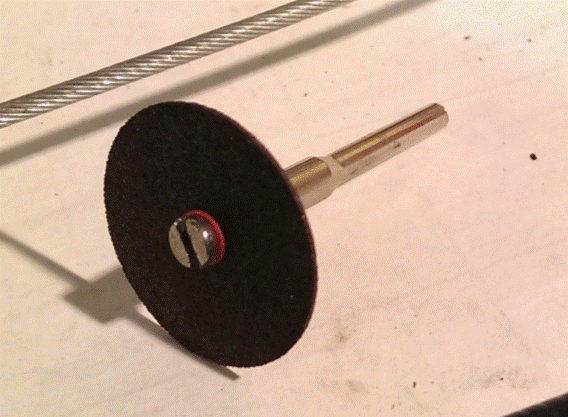
All this makes them a little tricky to cut. Good side cutters or a sharp chisel are usable, but cannot provide a square end; not strictly necessary, but if you want it, and a square end allows the ferrule to fit over more of the casing and to be retained more reliably, you can use a cutting disc in a Dremel or similar tool. This results in a neat square end, and the PVC, which will have melted somewhat can be cleaned up with a sharp knife.
Ferrules
The ferrules are often nickel plated brass or steel. They vary somewhat from supplier to supplier and may be brass and hard; or steel and soft. They should be a sliding fit over the end of the outer casing but if slightly tight their fitting can be aided with a little detergent or something more readily available (I usually use a bit of saliva! Good lubricant for rubber, saliva) they should not push the PVC out of shape when they are fitted.
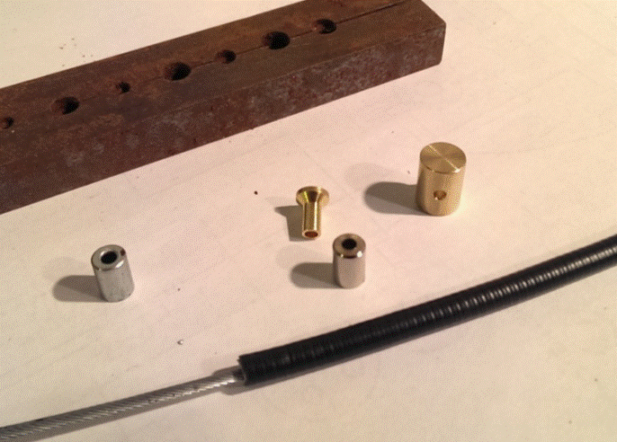
If they are tight, you might choose to leave them as they are; you can tap them in one place with a dot punch; you can crimp them with pliers. After I had made a few cables, and never been very satisfied with any of these methods, I made a simple swaging tool from two pieces of ½” square bar. The bar has a variety of holes, sized to suit the OD of the ferrules, less 0.5 mm. Therefore I have a series of stepped holes – the ferrule OD, and the ferrule OD less 0.5mm.
You will notice from the picture that this swaging tool, made from two bars, has the holes drilled such that they can be split. The modus operandi is to place the ferrule over the casing, and then place the ferrule in the tool such that the bottom 1/16” or so of the ferrule is gripped by the smaller of the two diameters in the hole.
The bars are then squeezed in the vice, and the ferrule is swaged such that it grips the cable outer casing. This works with all ferrule materials, but the harder brass ferrules are inclined to split when swaged. The steel ones work beautifully though.
First Nipple
Which nipple you fit first depends a bit on the installation. The trickiest part of making a cable is cutting the inner to the right length, at the second end. If you mess it up, the inner might be too short – in which case you have to start again; if you make it too long you just have to re-solder. So, I like to fit the most accessible nipple last. Usually this will be the handlebar end, but in this example I am making a front brake cable, which is very accessible both ends.
Fit the first nipple over the cable end, with the belled-out side away from the inner case ferrule. It should be a nice sliding fit on the inner cable.
The next step is to prepare the inner cable for soldering. It goes without saying that these control cables are vital for your safety and proper preparation of the cable, proper soldering (including selection of the solder) is vitally important!
There are two types of soldering technique to consider – hard soldering and soft soldering. Hard soldering involves the use of a solder containing a high proportion of silver, and temperatures up to 750°C. This involves the use of a hot gas flame and incurs the risk of annealing the cable (since most hard solders melt at a temperature higher than the tempering of the wire in the cable), leading to the possibility of the material yielding and the cable stretching - or, if you were foolish enough to quench it, the wire will harden and break potentially with catastrophic results.
Soft soldering on the other hand involves the use of solder containing various proportions of tin and lead, and temperatures of below 400°C, which will not risk annealing the steel wire. Soft solder can be heated using an electric soldering iron or a solder pot, and the temperature will be easily controlled avoiding the risk of oxidisation or weakening the wire.
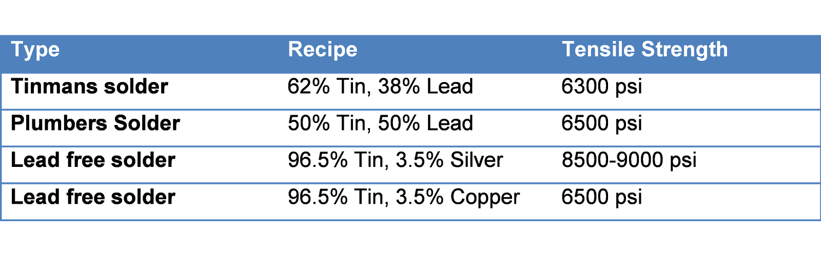
Soft solder is made in a variety of ‘recipes’ for various uses:
You will note that the solders listed vary in their strength according to the constituent components. A Lead free Tin/silver alloy is the strongest and therefore the most suitable for our purpose these solders melt at 250-300°C, suitable for a conventional soldering iron.
Solder is available in bars and wires, both with flux cores and without. I use non-cored wire solder, since I like to be able to control what flux I use.
So, you will need some flux. Metals at higher temperatures are even more prone to oxidisation than usual – so we need something to prevent oxidisation during soldering, otherwise the solder joint will be weak and will fail.
The impurities can be removed by mechanical cleaning or by chemical means, but the elevated temperatures required to melt the filler metal (the solder) encourages the work piece (and the solder) to re-oxidize. This effect is accelerated as the soldering temperatures increase and can completely prevent the solder from joining to the work piece. I like to use the liquid, Zinc Chloride based ‘Baker’s Fluid no.3’ for making cables, since it flows into the joint before any heat is applied and seems to be able to keep the join clean enough to ensure a successful joint every time. It's acidic, so you don't want to drop it on anything important (like a chrome wheel rim) and you will need to clean it off afterwards.
Now, onto soldering the first nipple. Again, we use our swaging jig which has a number of holes drilled through it of such a size as to grip the inner cable, without crushing it. In the top of each of these holes is a small well of larger diameter, used to form a ball, or birds nest, on the end of the inner cable. We start with the inner cable in the swaging jig, with a length equivalent to about four diameters of the cable sticking out above the well, the jig is clamped in the vice, and the inner cable is not going anywhere.
Using a punch, we tap down on the end of the inner cable, in order to divide the strands:
Having divided the strands down into the well, we take a pair of long-nose pliers which, together with a small hammer, we use to bend the ends of the strands back toward the centre, forming a ball:
This is where the strength of the cable assembly comes from. The ball prevents the inner cable pulling through the nipple, and the separated strands provide a hugely increased surface area for the solder to grip the wire, such that the tensile load in the cable is pulling on a ball of solder and wire which cannot pull through the nipple.
So, now we can remove the swaging jig and see that the wire nest fits nicely inside the nipple. We are ready for soldering. Hold the inner cable in the vice, gently, such that the nipple is pointing downwards. We want the solder to flow into the nipple and to stay out of the inner cable; otherwise the inner cable will become stiff and your lever action will be affected.
Lead rich solders are more reluctant to flow than tin rich solders. You may find it more effective to leave the ‘cup’ in the nipple upward using lead rich solder.
Dip the end of the cable and the nipple in the flux, and apply your soldering iron. It will take a while to heat the nipple up, but occasionally touch the wire with solder to see if it is hot enough. Remember that the work has to melt the solder – the soldering iron is used to heat the work, not the solder. If the solder will melt when it comes into contact with the nipple, then the nipple is hot enough. Proceed right away, since overheating will produce more oxidisation and will ruin the joint. Allow the solder to wick down the cable, filling up the birds nest in the nipple. Let it flow until it is about to drop out of the nipple, and you’re done. Leave it to cool - do not quench it and do not move the end, or you will lose the pool of solder within the nipple.
You'll find it much easier to solder the nipples if you have a solder pot, like this one:
The solder temperature is thermostatically controlled, so there is no danger of overheating the wire and the solder will flood the joint easily. Overheating will ruin the heat treatment of the wire - in the picture, I'm showing a clutch cable that has been rendered brittle by overheating the nipple. The cable fractured just behind the nipple, leading to a ride home changing gear very carefully and hoping for light traffic - the same breakage in a brake cable could have been very different.
Once cool, clean all the flux off with water. Flux is highly corrosive and you don’t want damage arising from yet more oxidisation. File any excess solder away, and don’t worry if you file off the ends of some strands that are poking out.
Second Nipple
Once we have soldered the first end, we can fit the cable back on the bike. Make sure that all the adjusters are in their shortest position, and wind them out two turns. We are going to make the cable as short as possible but in the event that we are a little over-enthusiastic and we make it too short, we want to be able to loosen the adjusters more if it proves necessary.
Make sure you fit the cable in its proper routing and that the second nipple is properly located in the brake lever, carburettor slide or whatever. Now, you will need to have the parts in their operating position to get the inner cable length right – throttle twist grip rolled shut, throttle slide down; brake handlebar lever fully ‘off’, brake plate arm moved such that the brakes are almost on, but not biting. You want the brake, clutch or throttle in a position where a small amount of cable movement will have it operating with the adjusters wound ‘in’ otherwise the cable will be over length.
Mark the inner cable with a small piece of masking tape in the location you want it cut – but don’t cut it yet. It’s helpful when cutting cables if they are ‘tinned’, that is, if the strands are bound together with ½” or so of solder. Fit the second nipple and keep it out of the way with a piece of masking tape. Dip the end in flux, apply your soldering iron and when it is hot enough, touch the cable with solder and allow the solder to wick up the strands. Now it won’t unravel when you try and cut it. Use a sharp pair of side cutters or the Dremel cut-off wheel for this job.
Next, you can put the second end in the swaging jig and prepare the birds nest. Solder up the second end as before
Try it back on the bike, and use the adjusters to take up any spare length. If you have to unwind them considerably to get the brake, clutch, throttle or whatever workings correctly, consider releasing the second nipple and making the inner cable a little shorter.
Lubrication
Decent lubrication is vitally important to the operation and life of a cable, and to the pleasure of riding the bike. I use one of these clamp on cable oilers with WD40:
Cable Management
Several methods of cable (and we are talking both control cables and electrical cables here) management were used in the 1950’s & ‘60’s, some more obvious than others, some more effective than others.
We are all familiar with the modern nylon cable tie, but whilst this is available in a wide variety of shapes, sizes & colours it is not in keeping with a 1950’s machine. That said, I have several on my Bantam and very effective they are.
You will find pictures of these black rubber ties in the BSA parts book for the Bantam. Originally made from Butyl rubber, they perish very quickly and fall off; modern versions are made from silicone rubber and will survive oil, petrol and sunshine very effectively

They can be used in a variety of ways giving the opportunity to strap cables of various diameters to handlebars, frame tubes or mudguard stays, and are used by passing the ‘T’ end through the hole in the opposite end, trapping the cable against the frame or passing the T through the middle hole, around the cable, and then again around the frame and into the end hole, holding the cable away from the frame. This looks rather neat I think.
Ariel made use of some rather neat steel sprung cable clips. Here are two three-cable originals on my W/NG, retaining the rear brake switch wiring - there are further ones under the tank retaining the clutch, throttle & air cables. These clips are available in stainless steel for one, two or three cables: