
For a while now I have been looking at YouTube videos relating to model engineering, thinking about an LBSC 'Tich' 2 1/2" gauge steam locomotive I started to build while still at school. I've looked at lots of videos of folk building & repairing Stuart Turner steam engines and have been toying with the idea myself.
The thing is, what is the point? I don't want something that gathers dust on a shelf. My son suggested that we build a steam bicycle and I have started to look at some calculations and have even considered a suitable engine... but these things are expensive if you build from a kit. Not that that is necessarily a barrier, but one wouldn't want to make a mistake with expensive castings. That idea may grow, or it may not. We will see in the fullness of time.
However, I still have a bit of a hankering to build something from a kit, but something I can use. I'd like to see what kit suppliers provide, and I'd like to experience having someone provide the materials and the drawings for me to follow, rather than supplying and maintaining the momentum myself.
I've read of folk recommending tools made from Hemingway kits and have looked at a few myself. I decided to take the plunge and bought what is probably the smallest kit in their lists, the Machinist's Hammer. It's described (and you can buy it) here:
http://www.hemingwaykits.com/acatalog/Machinist_s_Hammer.html
I don't have a hammer around the lathe - I always reach for the 1/2 lb engineer's hammer on the metalwork bench, but hey, let's have a go. The kit was ordered during lockdown and Kirk at Hemingway responded very quickly. The kit arrived in a couple of days.
Two packages of materials came in a large jiffy bag, nicely wrapped with a two page set of instructions and a drawing printed on good quality A3 paper.

There are various bits:

The instructions give you a work plan which I shall largely follow, with the exception that they suggest using a mill to drill the central hole through the head, followed by an end mill to machine the registers for the handle and the nut. Since I don't have a mill, I will hold the head in the four-jaw chuck and machine the registers with a small boring bar.
There's always more than one way to achieve something, and one of the most interesting things about making stuff is figuring out how to do it with the tools at your disposal.
The thing is, what is the point? I don't want something that gathers dust on a shelf. My son suggested that we build a steam bicycle and I have started to look at some calculations and have even considered a suitable engine... but these things are expensive if you build from a kit. Not that that is necessarily a barrier, but one wouldn't want to make a mistake with expensive castings. That idea may grow, or it may not. We will see in the fullness of time.
However, I still have a bit of a hankering to build something from a kit, but something I can use. I'd like to see what kit suppliers provide, and I'd like to experience having someone provide the materials and the drawings for me to follow, rather than supplying and maintaining the momentum myself.
I've read of folk recommending tools made from Hemingway kits and have looked at a few myself. I decided to take the plunge and bought what is probably the smallest kit in their lists, the Machinist's Hammer. It's described (and you can buy it) here:
http://www.hemingwaykits.com/acatalog/Machinist_s_Hammer.html
I don't have a hammer around the lathe - I always reach for the 1/2 lb engineer's hammer on the metalwork bench, but hey, let's have a go. The kit was ordered during lockdown and Kirk at Hemingway responded very quickly. The kit arrived in a couple of days.
Two packages of materials came in a large jiffy bag, nicely wrapped with a two page set of instructions and a drawing printed on good quality A3 paper.

There are various bits:
- a piece of aluminium round bar for the aluminium pein
- a piece of bronze for the hammer head and the bronze pein
- a a piece of 1/2" round steel bar for the handle
- a short piece of 1/2" round steel bar for the nut which holds the head to the handle

The instructions give you a work plan which I shall largely follow, with the exception that they suggest using a mill to drill the central hole through the head, followed by an end mill to machine the registers for the handle and the nut. Since I don't have a mill, I will hold the head in the four-jaw chuck and machine the registers with a small boring bar.
There's always more than one way to achieve something, and one of the most interesting things about making stuff is figuring out how to do it with the tools at your disposal.
Starting with the aluminium pein, we face and centre drill:

Then we can bore to 1/2", making sure to break the edge with a small chamfer:

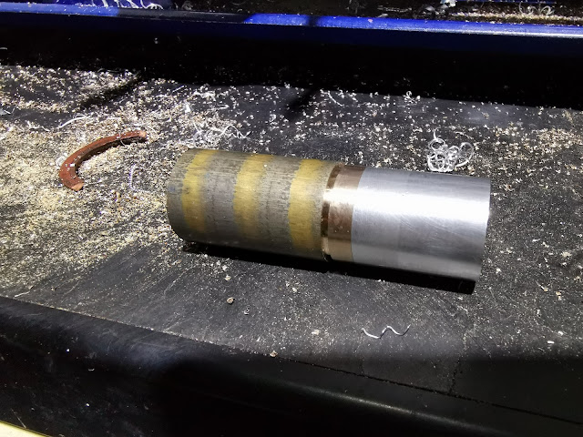
Next, we chuck the bronze head & pein and mark off for the 5/8" pin:

Before we go any further, it's good to check the run out. I usually get to about 0.01 mm:

The bronze is easy to turn with carbide at high speed, but the chips are sharp and go everywhere:

The aluminium pein is held in place with high-strength Loctite and pressed home with the tailstock during curing:

Next, we make a decorative groove with the parting tool and turn down the aluminium pein to the finished diameter:

That's it for now - but I should have drilled the cross-hole at this point...
This is a new technique for me - turning between centres. I made this lathe dog to use with my new faceplate to turn the long taper on the hammer handle.

Here's the dog and it's drive pin:

Before we turn the taper though, we will need to machine some other features of the hammer handle. The head is held in place with a special nut which we will make later, but first the handle needs a 5/8" length of M6 thread. Here, I'm turning the shoulder for the head to sit on and the parallel pin for the thread:

With the thread cut using my tailstock die-holder, I take the handle & hold it in a nut in the vice. I want to paint it with Dykem to mark out the features I have to machine:

First, I have to cut these three rings using a 1.5 mm parting tool. These are partly decorative and partly for grip:

While I have the three-jaw chuck on the lathe, I will make the nut. This is just a bit of 1/2" round bar, with an M6 thread to match the handle and a screwdriver slot; it's got a reduced diameter to fit in the head producing a shoulder to retain the head.
Cutting the thread with a spiral flute tap - I'm turning the lathe by hand:

Parting off. The lathe is much more rigid with the new cross slide gib strip:

Cutting the slot with a hacksaw and a needle file:

Having completed the nut, I removed the three-jaw chuck from the lathe. The aluminium pein of the hammer head has a fine turned finish and I wanted to use the ER40 collet to avoid damaging it. First job is to turn the second groove in the correct position and to the same depth as the first one:

Next, we turn it to 1" OD and finish at high speed.

That's the turning finished, but the peins are slightly over length:

The ends are 'crowned' with a file to give this raised dome:

Now on to the hole for the handle. I'm drilling it in the four jaw chuck, which just about accepts it; it's easy to get the centre point longitudinally between the two grooves, but radially is a bit more difficult. I'm using this knife blade which is both flat and hard - it will tip if the centre is not exactly aligned:

Here I've just finished the 7/16" hole through the middle, nicely on-centre. I wish I had drilled this before I did the finish turning - the chuck jaw marks are quite visible.

The counterbores were made in the lathe, with a small boring bar:

The handle fits nicely:

The dimensions on the drawing don't give any tolerances - the nut is very tight in the head. I'll have to relieve it a little:

Before I get into turning the handles between centres, I want to modify the chuck guard so that it can still be used with the faceplate and drive dog in place. I've added a bracket to lift it upward and toward the tailstock:

Here, the tailstock is offset as far as it will go - not as far as the 0.167" specified in the drawings. I will have to pull the tailstock apart later.
This is the first time I have turned between centres - access is easy and it goes OK, but to use any speed the drive pin on the faceplate needs a counterweight. I make this with an M10 bolt and three nuts.

The counterweight works fine up to about 800 rpm, which is handy because the long taper takes ages to turn. I use the power feed to save effort and improve the finish:

I polish the handle in the lathe, with some 120 grit emery tape:

It's almost finished now. I need to trim the aluminium pein to length and polish out the marks I made with the chuck jaws.
That done, I can trim the handle to length and make the hemispherical end with a combination of taper turning on the compound slide, filing and polishing:

And that's it!


