Showing posts with label rocker cover. Show all posts

Thursday, 28 November 2024

FH - engine finished

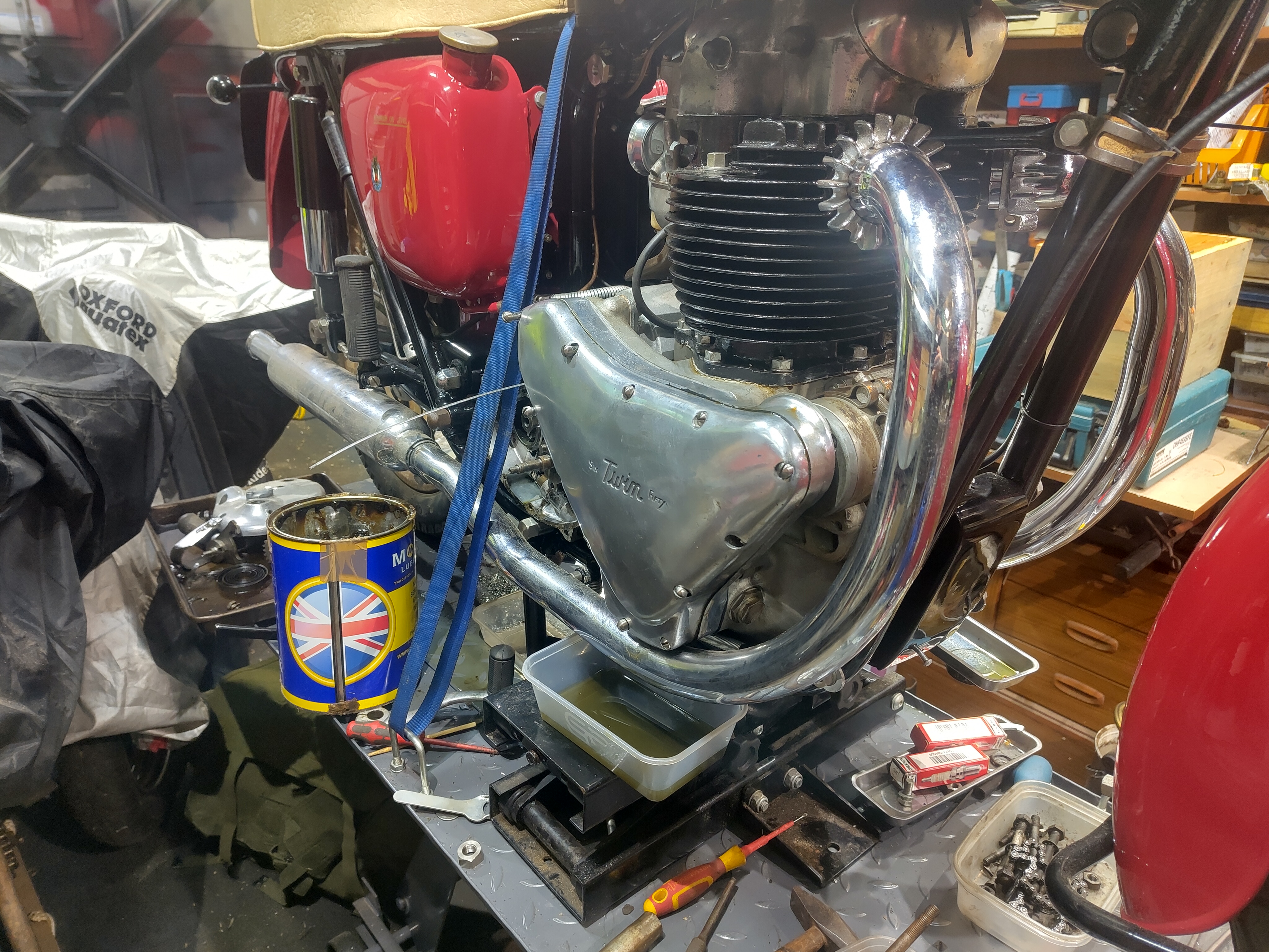
 Yesterday I spent a bit more time attempting to finish the tappet covers. After clearing the threads in both the covers, clearing out the locating pin holes and straightening one of the locating pins on the inlet I finally got them to fit. The part numbers are identical for both inlet and outlet covers, but for some reason the one I had on the inlet fits the outlet and the one I had on the outlet fits the inlet. Go figure. There's obviously something around the locating pins, and I did notice that the original centre screw is longer than the one that I made; however, they are both on and done up and finished. 

Next I moved on to the timing cover with Wellseal and grease either side of the gasket as this cover comes off fairly regularly. 

The dynamo chain area is now liberally coated with semi-fluid grease and the cover is on. Some of the screw holes are obviously not clear for their full length and now that I have new Acme stainless steel screws I will need to run a tap through some of those holes again. I've ordered a tap from Tracy Tools - they do a very long (and expensive) tap called a 'nut tap' which will do the job nicely. 

The 'nut tap' is a very long taper tap - I'll need to cut perhaps half the length off the taper, as I really need it as a plug tap.

Next step is to close up the gearbox. I'm on the railway for the rest of the day, so that will have to wait until tomorrow.

One job I haven't really finished is the head steadies. Unfortunately despite the fact that they are retained to the head with half nuts, there is still not enough room to get a nut on the timing side - the drive side has a fin missing. It's extremely fiddly in there, there is no space, and unfortunately I have realised that you have to have the rocker cover slightly high before you can get the nuts on. I'll lift the rocker cover again next time. 

Thursday, 22 October 2020

Charlie's shed - Making bolts

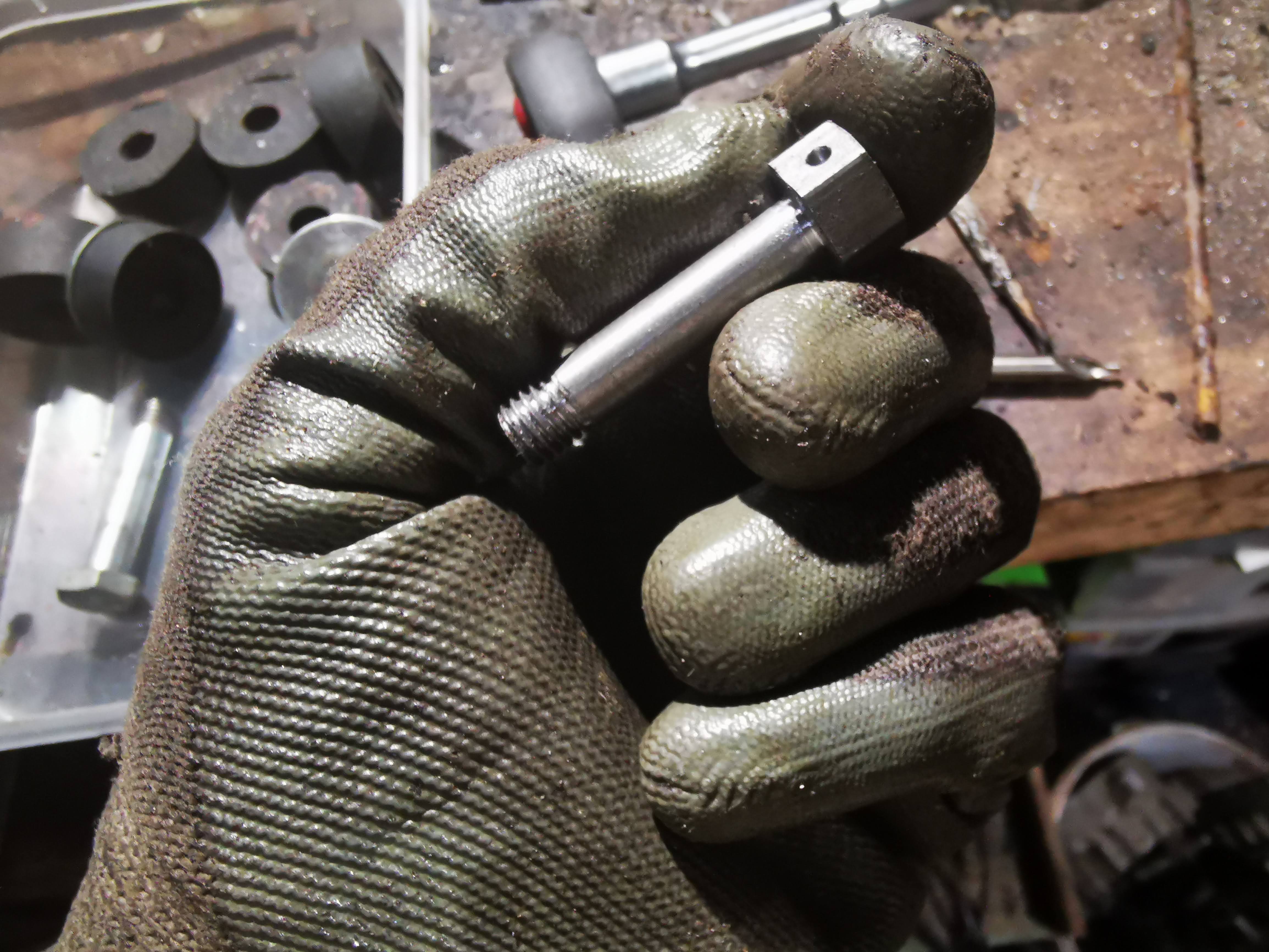
Pulling the rocker box off the exhaust side of the W/NG engine revealed that the bolt I had planned to copy, to replace the missing one, was too short. Since that came from the same position on the inlet side, I now had two new longer bolts to make. According to the parts list, the rocker box bolts are 2 5/8" and 2 7/8", both 5/16" CEI of course.


To make a couple of bolts I cut two pieces of 5/16" bar stock and a piece of 0.515" hexagon bar.


I drilled a 20 mm length of hex bar 5/16", to make the bolt heads and parted them off to a thickness of 6 mm.


Setting them up in the vice, I joined the heads to the bolt with an autogenous weld - the welder was set to 30 A.


With the heads in place, I parted the bolts to length. With the same setting, I threaded the first 3/8" of the bolt using a tailstock die holder to ensure the threads were parallel:


Like this:


I use this Molyslip cutting compound for thread cutting:


Since the bolts were slipping in the chuck, I cut the remainder of the thread in the vice:


With the thread done, I put a small chamfer on the bolt head.


The two finished bolts are shown in the centre, with two short ones top and bottom:


Whilst we have the Whitworth hexagon bar out and the tailstock die holder in the lathe, we'll take the opportunity to replace the missing tank bolt. The W/NG has always had M8 tank bolts, replaced some years ago by me, after I found and temporarily repaired the holed tank - the previous owner had replaced the original bolts with M8 screws and had managed to puncture the tank in four places - the story is here. I made some new tank bolts from very long, standard M8 bolts cut down and threaded for a very short length, so they could be done up tight and not puncture the tank again. Because I'd used standard bolts, there isn't much room to drill the heads and at some point in time one of them had gone missing. Again because I'd used standard bolts, they had 13mm  AF heads and none of the on-board spanners would fit, which was a nuisance - I had to use the adjustable which the W/NG carries in it's tool kit.

So, I resolved to make a new one, using this 1 7/16" tank bolt from the Model A as a prototype:


I have a bit of 0.515" hexagon bar in the lathe, and I have reduced a length to 8mm diameter, cutting the thread to a suitable length using the tailstock die holder to ensure the thread is concentric with the bolt axis.


I parted the head off to a length that matched the one from the Model A, and set it up in the pillar drill to drill a wire locking hole. I started the hole with a centre drill and used a 2 mm drill to go through.


I put a small chamfer on the head of the bolt, to remove the corners, and that's it.


I need one more of these for the W/NG, and two at 1 5/8" long to replace all the modern ones - then I will chemically black them. I also need one for the Model A, though this will use the original 5/16" BSW thread.

Thursday, 15 October 2020

W/NG - Assembling and fitting the head

I finished the last post with the cylinder head paint drying, and I went and had a day on the railway which I recorded in this blog post so that now, the paint has been curing for a couple of days.


It's dry but not very hard. I scrape the paint off the gasket faces with a Stanley knife blade, and set about cleaning the bolt holes with a 5/16" plug tap. Apart from this damaged one, they are all in pretty good shape.


Next stop, put the valves in. We know that these fit, because in the last episode we ground them in so this time it is a matter of fitting the valves, Halite washers, spring seats, springs, spring tops and collets. Collets are a bit fiddly to get in, so the best thing to do is put a lump of grease on the stem and then introduce your spring compressor. When you have the spring compressed, fit the collets with a small pair of pliers, tweezers or a chopstick with a bit of grease on the end:


Push them into place with the stick and slowly, gradually, gently release the spring compressor. Tradition tells us to tap the valve stem with a hammer to make sure the collets are seated and the valve/spring assembly is secure.

Next, check the head seal to the barrel. These engines have no head gasket, but the barrel is machined with a spigot which is ground into the head with grinding paste; the area around the spigot is machine a few thousandths deeper so the pressure from the head bolts is born by the spigot alone, sealing the joint. When you are happy that you have a clean joint all the way around the spigot, you can think about putting the head on - but before you do, you need to sort out the pushrod tubes and their seals.

This is the bottom seal - the old, compressed black one and a new one from AOMCC Singles Spares:


Here's the top seal. You see there is a shorter spigot here, which fits around the spigot pointing downwards in the head. I've assembled these dry, with no sealant:


With the pushrod tubes standing in the crankcase, you can drop the head in place, watching the pushrod tubes settle onto the spigots at the top. Next you can drop the 3/8" CEI head bolts in - which I have previously cleaned on the wire wheel. Tighten these down firmly - there is no recommended torque figure. when that's done, the pushrods can go in. When I dismantled the bike, I stored the inlet and exhaust valve gear separately, so I could ensure they all went back in the same place.


Next I took the opportunity to refit the exhaust, with Threebond 1215, and the carburetter - again with Threebond and a new gasket.


Don't forget to put the little caps back on the valve stems:


Next, you can seal the new gaskets (I'm using Draganfly's new aluminium gaskets) and fit the rocker boxes. Be careful with the bolts - three are the same length (about 2 5/8") but one, the one above the pushrod, is longer - 2 7/8". The one shown in this picture is wrong - it's a short one. The danger of this is that you will pull the thread if you overtighten it.


This looks easy doesn't it! What you can't see in this picture is that I had refitted the exhaust rocker box without aligning the rocker in the top of the pushrod. Later, when fitting the decompressor I found it wouldn't work, and I had no compression. What was happening was that the misplaced rocker was holding the valve open, and preventing the eccentric pin on the decompressor reaching the pad on the rocker. Secondly, one of the long rocker box bolts is missing from the exhaust rocker box, so that's two I have to find.

I've now managed to fit both rocker boxes without missing anything out! I've added the rocker oil line, and this time I have fitted a cable tie as shown in the parts book for this bike - it's very unusual to see these fitted.

There is still a rocker box bolt missing (two actually), which I will have to make. I've used the opportunity to introduce some oil into the rocker box through this hole - this is not normally possible, but recall that this hole has a chunk broken out of the head and so provides a passage from the bolt hole into the head and down into the pushrod tube. The objective is to get some oil onto the camshaft.

Saturday, 27 October 2018

Starting the Engine Strip

Inspection starts with a look at the rocker box. Both covers are present, one has it's captive nut, one is missing...

Here's an ugly looking stud and some cornflakes gaskets for general amusement!

All is well at the inlet. The cover stud is seized to the nut and has come out with it:


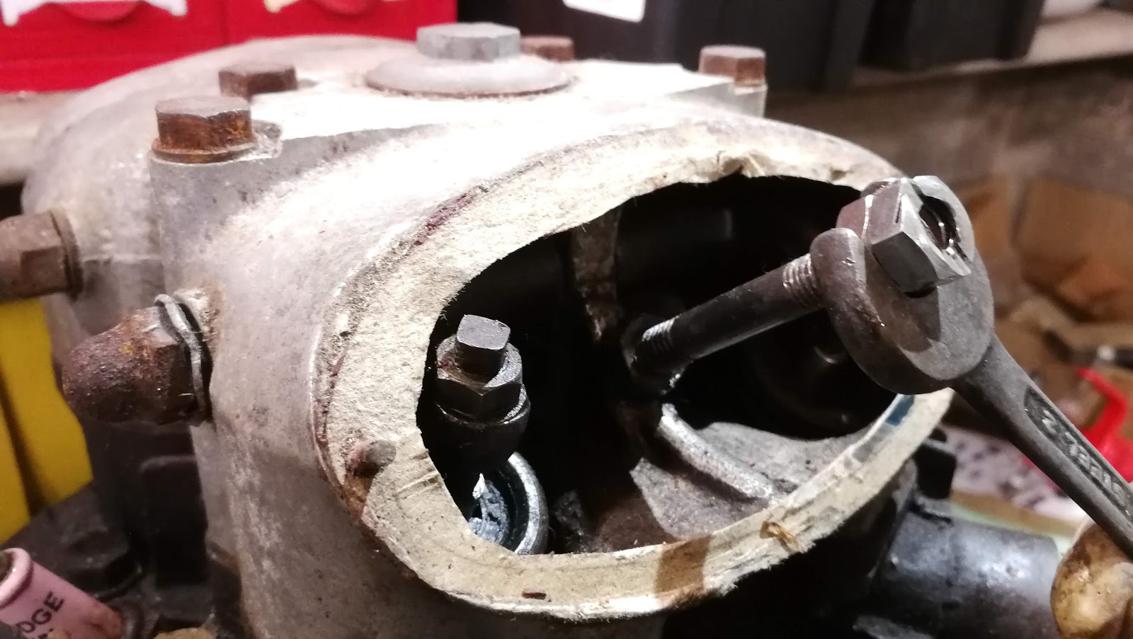
Removing the exhaust side stud with two 5/16" BSC nuts locked together:


Removing the inspection cover studs, we find one elegant Ariel stud with BSC threads at both ends, one 1/4" for the nut and one 5/16" for the rocker box. The other one, which has no nut is bent and is 5/16" both ends, one BSW, one BSC. Obviously a replacement but a shame, because the thread in the rocker box has been recut BSW. I'll be making a special on the lathe.


A stripped stud retaining (or not) the rocker box at the rear. Steve Carter, an AOMCC member who rides thousands of miles each year on his Huntmasters, uses a bolt here to avoid the worry of losing that nut down the pushrod tunnel:


General view of the head mating surface. All the springs look good at first glance:


Here's the underside of the rocker box:


More cylinder head general views:


Quick shot of the underside of the head. Looks OK, bolts were very tight but came out with some effort:

Bores and pistons. After I took this shot I gave them a quick clean up - the bores are unmarked and have no ridges; pistons have no undersize showing.

These are the dished pistons. Simon Gardiner (AOMCC) tells me that dished are the 6.5:1 standard pistons; if they had been flat-topped, they would be the the export/sports 7.25:1 pistons.

Friday, 22 August 2014

Oil Pressure

So as I have mentioned previously, my plan was to spin the engine up on the big power drill. I've now done this using a 1/2" square driver with a hexagonal shank in the drill chuck, with the drill set to 2nd gear - slow speed, high torque. The drill drives the engine through the crankshaft nut under the oil pump.


I connected a short hose to trap any fluids coming out of the oil pressure gauge line and take them back to the oil tank. Because of course the timing cover is off, there is a lot of oil in the drip tray which comes from the rear main bearing. 

The plugs are out to reduce the torque required from the drill.


And here it is:

Evidence of oil emerging from the return line. When the drill is running, you can see this pouring out, and you can see it at all eight rockers as well. Its noticeable that the inlet rockers get a lot more oil than the exhaust rockers - Ariel should have adjusted the size of the oil holes (smaller in the inlet rockers) to increase the feed to the exhaust rockers.

After a few minutes on the power drill, the bike is noticeably easier to kick over. Next I refitted the rocker cover studs and I put the tank and the oil pressure gauge back on and ran the test again looking for measurable oil pressure.

At maybe 250 rpm on the drill I am getting something like 25 psi.

Friday, 28 September 2012

Is it time to strip the engine yet?

Well, what delights will we find under here? 

Since I have not been able to shift the head, despite undoing all the fasteners (no I didn't miss any) I have decided to attempt to remove the barrel & head together and biff the head off the barrel using a block of wood from underneath.

Thanks to the ever-helpful Brenton Roy for that most excellent suggestion!!

The only challenge is that now I must undo all the cylinder base flange fasteners, several of which are inaccessible due to the dynamo and the timing cover. So, off with the timing cover! Unfortunately my imperial  hex keys were not at home - so I had to wait a little while. It's interesting that someone has fitted a set of cap head screws to this engine, so it's likely that someone has been in here before - which I guess is almost inevitable on a 60 year old machine. 

However, it comes off very easily, apparently with no stripped threads, though there is a quite a lot of Red Hermetite about.

Here's what I found:

Nothing too appalling at first glance. Everything in it's proper place, nothing mangled, the chain looks good and the tensioner is all there.

It's quite dark though. Is this evidence of a lot of blow-by I wonder?

Looking a bit closer, there is quite a bit of wear where the chain tensioner bears on the case - but this is probably normal and inevitable since the blade is free to flex at this end and the chain tension forces the blade against the soft aluminium case.

I'm not too worried about that.

But see what is missing? I didn't remove the nut on the end of the dynamo drive shaft! It's gone! Thankfully, unless it is stuck to the inside of the timing cover (I haven't looked yet) it must have been lost last time the engine was apart. There doesn't appear to be any damage from it flying about inside.

What else?

This is a bit peculiar - the tab washers for the oil pump haven't been bent up.

The alloy block and the two plungers are free - we will have to see what tolerances are specified for these parts.

Next stop we need to figure out how to time the engine so we can put it back together. Then it is dynamo off, oil pump off & we will attempt to remove the barrel  What fun! I might do some polishing first through, so I can clear the bench of the rocker covers and timing case.


Tuesday, 11 September 2012

Labour of love

Going through the grits, page one of thousands...

There has been no time this week to take the head off yet - it is still sitting in the summer house awaiting hours of patience with an open ended spanner, but we can finish cleaning up the rocker covers.

I haven't committed to any polishing equipment yet, but with a spare hour I have started to polish the two rocker covers by hand.

Starting by scraping off the dirt with the ubiquitous credit card/hotel room key, we move on to 240 grit used wet to cut back most of the oxidation. Moving through 400, 600 & 800 stopping periodically to ensure that the whole surface is cut to the same standard.

For some reason we seem to be out of 1000 grit, but we move on to 1200.

The next step is a waste of time - we try with some Farecla G3 cutting compound, but quickly find that this will not cut aluminium. It is an excellent product for what it is made for - paint & lacquers.
For final finishing - Solvol Autosol, resulting in the shiny parts we see hereabouts. Shiny enough, not to ruin the patina of a 60 year old bike? too shiny? not shiny enough?

You be the judge.

More next time...