Showing posts with label breather. Show all posts

Saturday, 16 December 2023

FH - Engine breather

 The engine breather on the FH is similar to that on the BSA A10 & A7 and is comprised of a timed vent driven by the idler wheel in the timing chest, ported through the crankcase joint behind the camshaft space to an outlet ahead of the gearbox sprocket.  There’s a little copper pipe which arrived like this:


It’s not supposed to look like that. It’s supposed to be like this:


In the days before the FERC arrived, this pipe was led to a gap in the alloy arc cast on the back of the primary case to protect the gearbox sprocket, so anything coming from the breather lubricated the chain. When the FERC arrived, the breather pipe didn’t change as far as I can tell but as you can see it can’t get to the gearbox sprocket any more.

We’ll direct it downwards.

First step is to anneal it by heating it cherry red and quenching in water:


I want a bend, just less than 90° to direct the gases downwards. I use the little pipe bender to make a tidy job of that:


I added a bit of 8 mm fuel pipe to a level fractionally below the lower frame rail. 


That will do nicely.

Sunday, 10 December 2023

FH - bottom end complete

A little bit later than expected I am back in the workshop. My generator decided to burn out it's alternator winding, and took the battery charger with it which meant buying a new generator, building a trolley for it (it doesn't fit where the old one was) and building a trolley for the welders - because their spot is now taken up by the generator...

Having got most of that out of the way, I can strip the cases again to fit the replacement connector rod nuts, BSA part number 37-1691. These are genuine new old stock from Vale-Onslow. Looking at the picture below, from left to right we have the modified Draganfly nut, an unmodified nut, and on the right the new lower profile nut:


This, by the way, is the mark left by the Draganfly nuts before I modified them:


Here are the Draganfly big end bolt washers. These are laser cut stainless and whilst some suggested they were rather small, they are much the same size as the bearing surface of the nut so I am leaving them in place.


Stupidly, I forgot to picture the new nuts in place on the big end caps. Mrs H phoned to see where I had got to (I'll just be 10 minutes dear!), and that's always a distraction. Suffice to say that they were torqued up to 22 lbf. ft in accordance with the BSA data sheet and I oiled up the various bearings before closing the cases. I made sure to remove all traces of Threebond and was very sparing with it when reassembling.

The case bolts are all stainless, from Acme as usual and they fit beautifully. I made this chart from the diagram in the Draganfly catalogue to show me where the different bolts go:


Lovely and easy putting them in; I used my frame spreader to make it a bit easier.


Now that the bottom end is in, we've got a number of workfaces to tackle:
  • the barrel and pistons
  • the primary case
  • the timing gear
We can look at any of these really but before we do there are some components around the engine that will become less accessible as we progress. The first of these is the engine breather shown here in the form in which it arrived:


This isn't how Ariel designed it. It's supposed to bend around and appear behind the FERC, above the gearbox sprocket somewhere.

Another item is the magneto. It's fitted here temporarily with the long bottom nut, which is on the job list for zinc plating. With the primary case loosely bolted in place you can see that it's quite restricted in there:


Something that surprised me, and thanks to Daniel Rix on the FH Facebook page for this, is that you cannot get the brake bell crank on with the primary case in place. That's a pain, because I want to get on with the mechanical build and I hadn't planned on doing any plating just yet... and the bell crank needs plating.

The other thing I must remember is to fit the oil lines before I fit the primary cases! Access will be a trifle difficult if I forget, so let's not get ahead of ourselves and we will get on with sorting out some of the details.

Friday, 3 June 2022

SQ4 - Oil Leak from the Rocker Feed

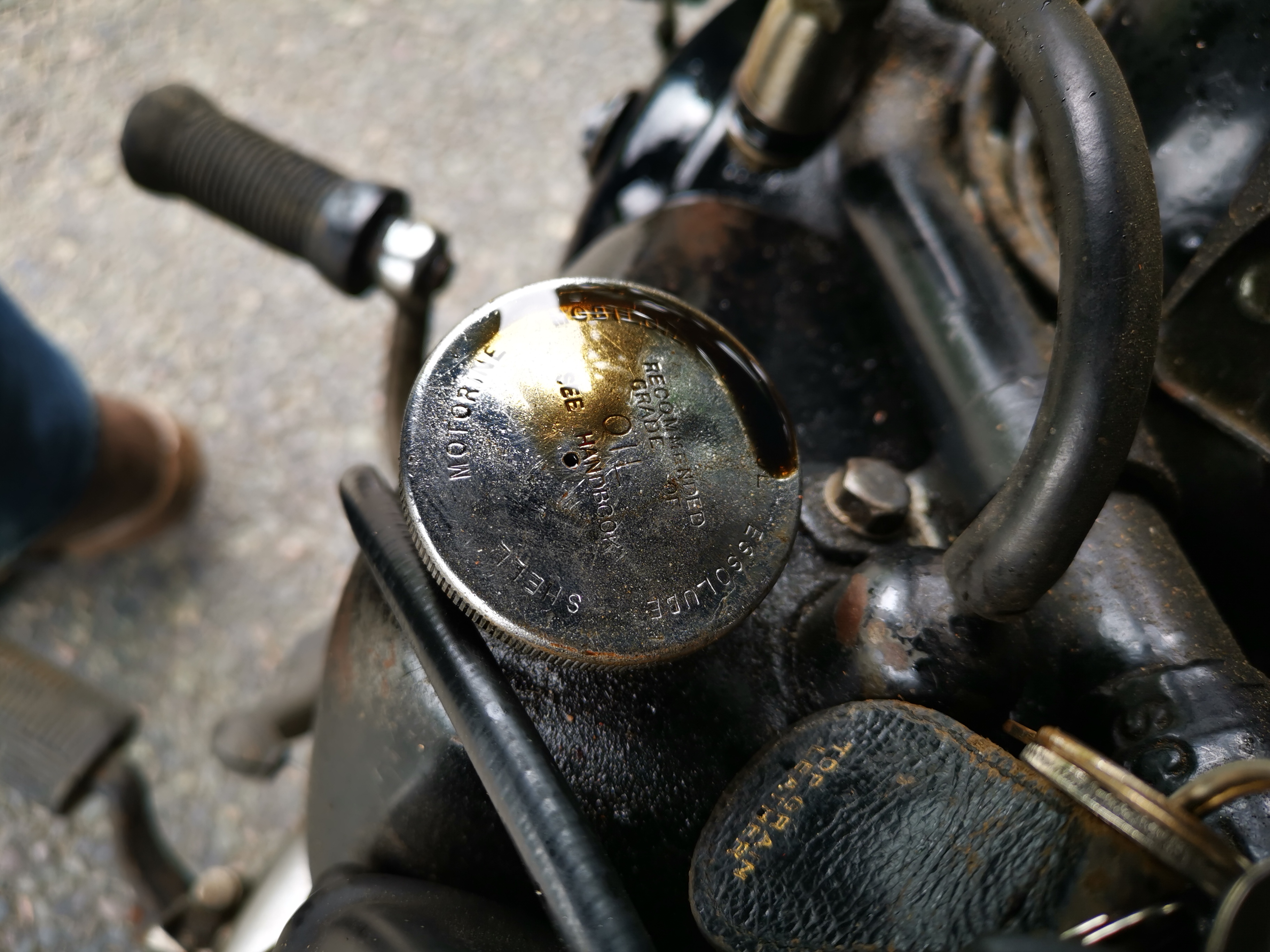
 This may be a seminal moment in the history of my SQ4. For years it's had an oil leak which I have always assumed to be poorly sealed pushrod tunnels at the head joint. However, having addressed a problem with a leak from the oil tank cap, something else which it has always done, I resolved to look at the drip from the rocker feed pipe. 

The oil tank cap has always had a weep from the breather:


Which translates to a wet leg on a long, fast run:

Looking at that first picture, I got to wondering why the cap has a vent hole when the tank has a piped breather that I have taken past the rear wheel. Surely the cap should be sealed?

It turns out that Square Fours don't use the same cap as other Ariels. I noticed that the 1951 SQ4 parts list has a -32 number for the cap - most bikes (other than Square Fours) I've seen use a -29 number. Maybe 5854-32 has no breather hole.

A blob of solder will sort it.

Onto the rocker feed. I ran the engine cold (75 psi on the gauge) and as the oil warmed up the leak appeared:

Now, my bad - I forgot to take a camera to the workshop when I fixed it. It turned out the tube was not pushed into the fitting at all - it was just held in place with a fillet of solder at one end, and had been like that for years - probably eight years. It's been leaking for most of that.

All fixed now.

Thursday, 8 November 2018

FH - inner timing cover

In the last instalment, we removed the outer timing cover to gain access to the dynamo drive, the ATD and the oil pump. We removed the dynamo drive chain but then stopped with this old, lightweight Japanese puller distorting itself while attempting to remove the large dynamo pulley on the idler pinion.


Over a week later, with three trips away for work I can tell you that the old puller never managed it and I had to make a new one. The new one, backed by a piece of 1" x 3/16" angle, is considerably stiffer though it loses out by having a coarse thread - the centre thread on a puller should be a fine, hard thread. Anyhow, it worked well enough and the dynamo pulley is now off.


Here we are - I told you it was off. Nothing untoward here apart from damage around the ATD which suggests it has been whirling around and rubbing the timing case:


The next step was to remove the inner case, which is held in place with four screws. A quick dose of the traditional remedy - leather hammer and impact driver, though not necessarily in that order, had it free in a jiffy. A mysterious 'tink' followed and this little chap appeared in the drip tray:


I wonder what it is?

Now we can see the crankcase, which looks fine & dandy. The idler will have to go back in to release the crankshaft & cam shaft nuts.


Here's the crankcase side of the inner timing cover. You can see the damage the loose ATD has caused in the top right of the picture.


And close up:


The magneto shaft, whilst it will turn the points, is very wobbly. This is more than a bearing problem - I think the shaft is broken.


Here's the timing cover in the parts washer, almost clean.


It was about now that I discovered you are not supposed to put paraffin (kerosene) in these little parts washers...