Showing posts with label valve. Show all posts

Thursday, 10 July 2025

SQ4 - under the tank

 I've taken the opportunity to remove the petrol tank because it's time I did the valve clearances and had a look at a persistent oil leak that has been going on for years. I thought it was fixed; I changed my mind and decided it was a head gasket problem - but then careful observation of the rocker box oil line revealed some seepage. It's obviously been quite bad in the past at some point, before I fixed it last time, because there's oil on the steering damper plates under the steering head. There must have been quite a jet to get it out there. 

Some years ago I did repair a leak here but it appears I didn't do it very well:

When I took this apart it was clear that they was some oxidization within the joint which had prevented the solder wicking down inside the fitting. I cleaned that up with wet and dry and tinned the pipe with some solder, using plenty of flux to sweat the joint into place. It resists that twisting now. 

The next job is to do the tappets and pulling off the rocker covers reveals some lovely clean valve gear. 

These are all supposed to be set to 0.001" with the engine cold. I used the famous 'Rule of Nine' to set them up. 

Valve clearances all proved to be very close to where they should be - I adjusted a couple of them but most of them were ok. I moved on to the spark plugs - cleaning them, checking their gaps but again they were all ok.


This one is from cylinder number 4, but it's fairly typical of all the others. You might think it's a little dark on the centre electrode and indeed we might consider adjusting the mixture a little. We could put another washer under the float valve to lean out the mixture across the whole rev range.

I took the opportunity to change the thumb nuts holding the HT cables to the plugs for some larger ones that I made some years ago.

With the rocker cover off I took the opportunity to snug down the head bolts and nuts. This is quite straightforward except for the pair that are buried in the fins - these two at the back are particularly difficult and you have to take the carburettor off to get at them. The one on the timing side of the bike is almost impossible because the casting has not been cleaned up sufficiently for you to be able to get at the nut.

Next time that I take the head off, there will have to be some grinding in there.

Reassembly was quite straightforward, apart from getting the oil tank back in. I've now 'adjusted' the area above the engine plate and below the frame rail with my favourite (small) hammer. It goes straight in now, but you have to remember to take the oil supply/return manifold off the engine first. You can't get the oil tank bottom bracket past the oil lines with the lines in place.

Saturday, 14 September 2024

FH - cylinder head refurbishment

 Inspecting the cylinder head of the Huntmaster revealed that the valves and particularly the guides were very poor shape. There was 2 mm of movement at the edge of the valves when they were in the open position - so they were going to have to come out.

As you can see a lot of carbon came out with them.


Feked provided a set of valves, guides and springs at a very decent price. I guess the fact that these are BSA A10 parts provides some economy of scale.


The new guides are 0.565" diameter; the old ones are 0.562". Guide bores measure 0.561 - 0.5615". The most interference we would want would be 0.0015”, especially if they are cast iron guides - and even at that they would need reaming to finished size after fitting. That means the guides need to be 0.5625 - 0.563 for a 1 1/2 thou interference fit or 0.562 - 0.5625 for a 1 thou fit.

It was quite tricky to take two thou off on a lathe whose bearings allow half a thou movement on the diameter but I persisted, setting them up with the DTI in the ER25 collet chuck which worked rather well. In the end I got them down to the required diameter.

With them all done and the oven hot after a chicken and chips dinner I decided to put them in one afternoon. The valve guides spent half an hour in the freezer whilst the head spent half an hour in the oven set to maximum. In the event the infrared thermometer showed a temperature of 248° C and I was happy with that.


The guides went in relatively easily with help from a small hammer and a drift made from aluminium and bought from Feked; this was ok but I thought a little soft and probably not worth the money. I should have made one from steel.

I discovered during the process that the spring seats did actually fit around the guides and not under them. I wish I had realised that (or at least checked) before I started the work.


The valve seats were badly pocketed as you can see in the picture below. There was really no choice but to recut these and I deliberated for a while over whether to do it myself or to subcontract work to someone else. In the end I don't know why I bothered contemplating it really because it always comes down to the same thing - I'll have a go myself.


Cutting seats in a cast iron head is not reputed to be particularly difficult and indeed these relatively cheap eBay cutters did the job. They did however leave some chatter marks which I was able to refine I gently re-cutting again and again and eventually I got myself to a point where I used the grinding paste technique to remove the last marks.


After a bit of grinding with coarse and fine pastes this doesn't look too bad.


However if you look closely in both of these pictures you can see that the marks are not completely gone and not wishing to remove the head again anytime soon or worse to burn my new valves I resolved to do something better.


I made this cone on the lathe complete with a half inch UNF thread in the middle to fit the same mandrel that the valve seat cutters came with. When I had mostly finished the cone on the lathe I put the mandrel with the cone fitted in the chuck and made my finishing cut on the cone to ensure that the cone was concentric with the mandrel and hence concentric with the valve guide.


That bit of cardboard in the foreground is the template with which you can cut the correct section out of the sheet of wet and dry paper. The system worked well and I was now able to fit the valves.

There's some cleaning up left to do on those gasket faces where I've overpainted a little but essentially the head is ready for fitting.

Sunday, 11 October 2020

W/NG - Cylinder Head

Now that the barrel is back on and the engine is timed, it is high time I started on the cylinder head. I've stripped it and done a bit of cleaning, and I know the exhaust valve and guide are very worn so I've got some new ones from AOMCC Singles spares. My plan is to get the paint on the head on and setting while I build the primary side, and I have checked over the clutch and ordered some parts from AOMCC Gearbox Spares to allow that to happen, but of course I need to do all the manual work (fitting the valve guides, grinding the valves and probably fitting them) to avoid damaging paint which will probably be soft for quite a while.

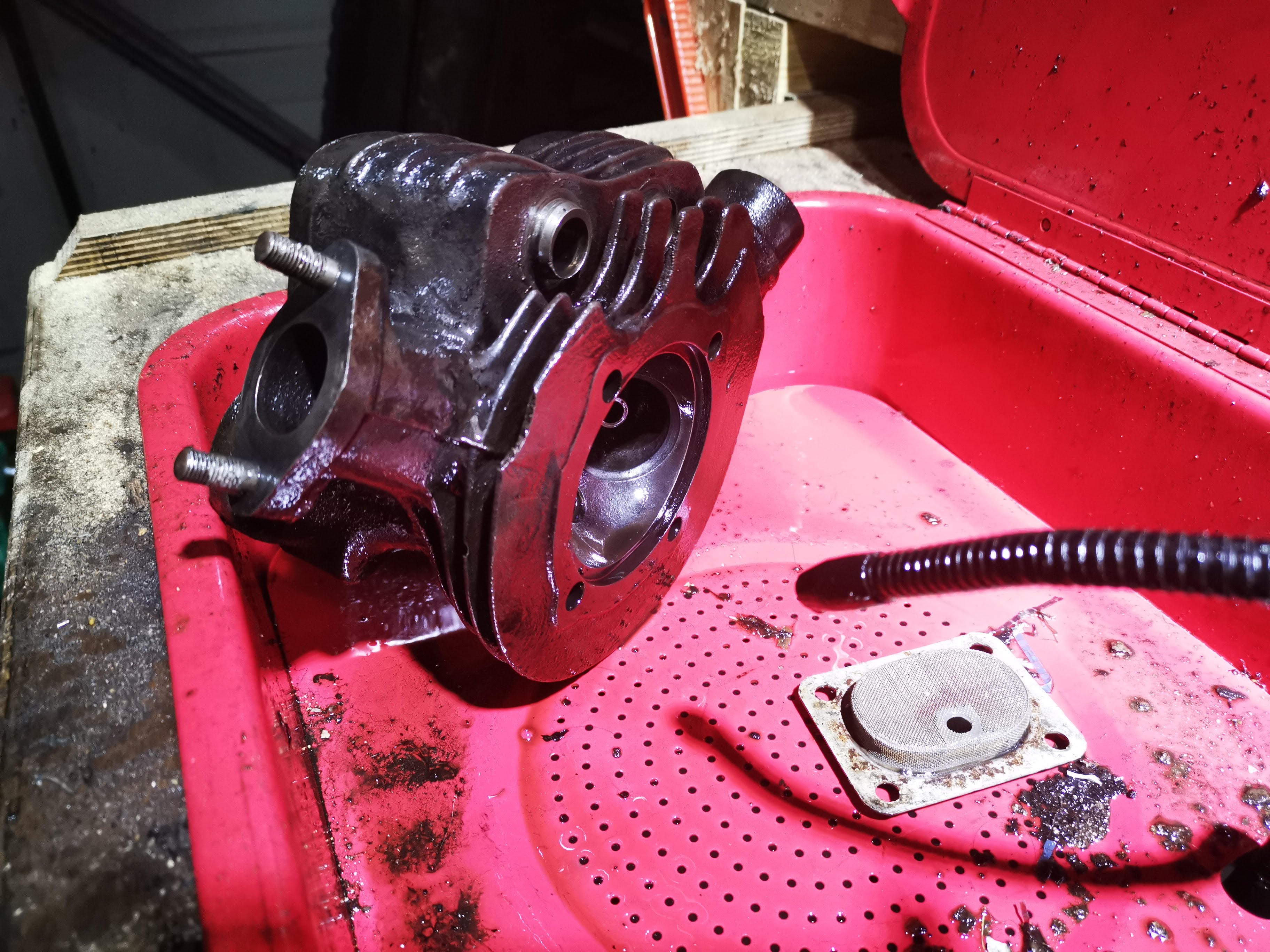
The head was pretty filthy, and after stripping it went in the parts washer for a bit of a clean.


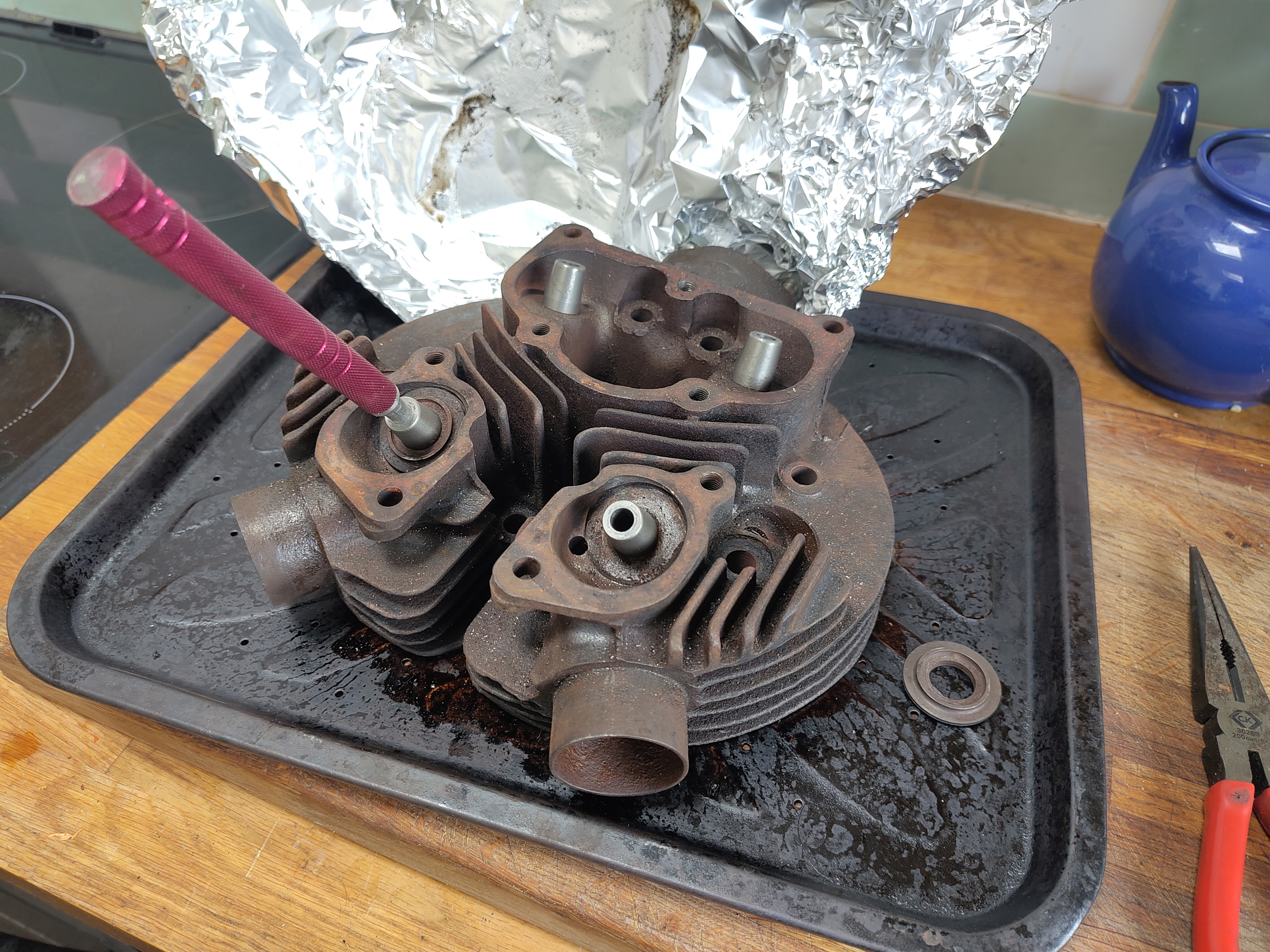
My first job was to put a taper on the inlet valve guide, which for some reason didn't have one. These are iron and machine very easily:


Still on the lathe, I made a drift out of some scrap 3/4" bar to support the mouth of the guide while I knocked them in to the warm cylinder head


With the guides in we can have a look at the valve seats. Here, I'm using the traditional 'sucker on a stick' to turn the valves against the seat - there is a smear of coarse grinding paste on the seat.


Another variation on this themes is a bit quicker, and not dissimilar to the suggestion in the manual - in terms of driving the valve stem rather than the head:


However you do it, once you have a continuous grey band around the seat with coarse paste you can improve the sealing capability with fine paste. It should end up something like this:


Now that the valve seats are good and I know that I can assemble the head after painting, I'll start cleaning up. I'll work it all over with a range of wire brushes:


But first off, let's get that greasy head back in the cleaning tank, and give it a dose of brushes and paraffin. I usually do this before I have to go off and do something else, like sleep, have dinner or do some building work so the parts have a chance to dry - this doesn't happen so well in the winter, so I sometimes get the propane torch out and dry them with that.


I'm using the same brushing engine paint that I put on the barrel - time will tell if that was a good idea as it is only rated to 200°C, but my temperature testing with the aluminium-head Square Four does not reach that figure. We will have to see what a thrashed iron head will do.


For the record, I put a couple of coats on the head on the 11th October. It dries in a couple of hours, but I will wait a day or two before starting to assemble it.


Post script: as of November 2022, after a fairly active and very hot summer, the paint is still intact and is showing no signs of distress. 

Monday, 3 August 2020

W/NG - time for some serious engine attention

As some of you may know, the W/NG hasn't been too happy recently - it's been consuming spark plugs at an alarming rate and has caused several unscheduled stops by the roadside - particularly annoying, because I'm lucky enough to live by the sea and a bike is the best choice of transport in the summer - you will never find another parking spot for your truck again if you choose to move it.

So, the W/NG is the go-to machine for local use, until it decides it isn't going to play nice any more. Next up is the SQ4... which has a flat battery and knackered points (my fault - embarrassing story), so now I know what a garage full of dead Ariels looks like:


So I've pulled the W/NG apart.


The rocker boxes come off easily. There is some head damage around one of the bolt holes, which I will probably leave well alone:


The piston is an oily mess and the top ring is in three pieces:


The small end is cratered but is dimensionally OK. I've not measured the pin or the piston yet, but the bore is 2.871 in the middle of the stroke (fore and aft direction) which is getting on for 40 thou over factory standard. There is no ridge at the top, so we will have to see what the piston dimensions are.


The valve guides are awful. I've not measured the valves yet, and I have no way to accurately measure the guides but the exhaust valve rocks maybe 1-2 mm at full open, the inlet maybe half that. The inlet guide is loose.


Then there is the big end. I can feel up and down play of maybe 0.5 mm; side to side rock is maybe 3 mm at the small end.

All in all, a good afternoon's work. A lot nicer than the morning, which was spent pulling one of these apart:


Saturday, 27 October 2018

Starting the Engine Strip

Inspection starts with a look at the rocker box. Both covers are present, one has it's captive nut, one is missing...

Here's an ugly looking stud and some cornflakes gaskets for general amusement!

All is well at the inlet. The cover stud is seized to the nut and has come out with it:


Removing the exhaust side stud with two 5/16" BSC nuts locked together:


Removing the inspection cover studs, we find one elegant Ariel stud with BSC threads at both ends, one 1/4" for the nut and one 5/16" for the rocker box. The other one, which has no nut is bent and is 5/16" both ends, one BSW, one BSC. Obviously a replacement but a shame, because the thread in the rocker box has been recut BSW. I'll be making a special on the lathe.


A stripped stud retaining (or not) the rocker box at the rear. Steve Carter, an AOMCC member who rides thousands of miles each year on his Huntmasters, uses a bolt here to avoid the worry of losing that nut down the pushrod tunnel:


General view of the head mating surface. All the springs look good at first glance:


Here's the underside of the rocker box:


More cylinder head general views:


Quick shot of the underside of the head. Looks OK, bolts were very tight but came out with some effort:
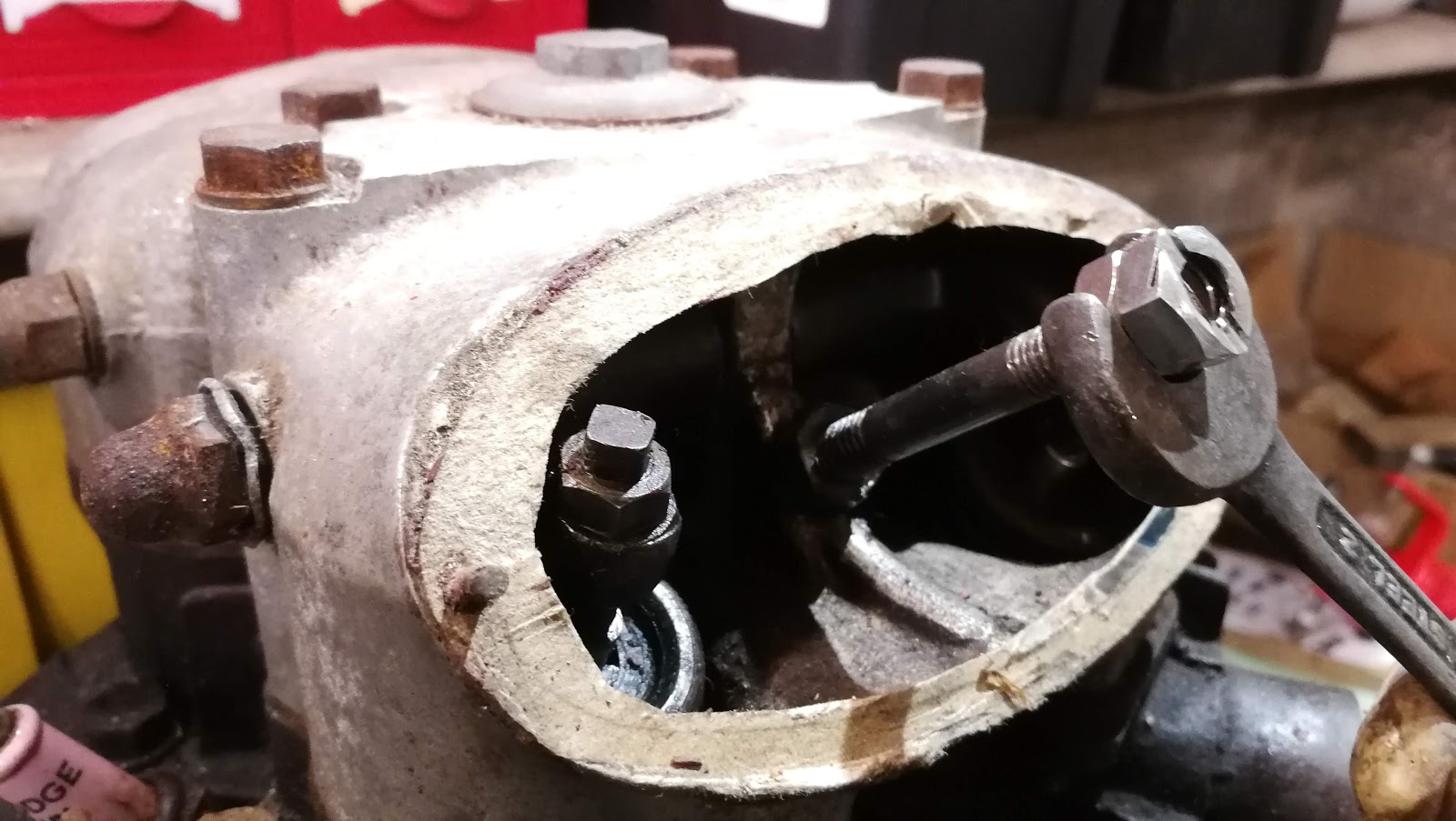
Bores and pistons. After I took this shot I gave them a quick clean up - the bores are unmarked and have no ridges; pistons have no undersize showing.

These are the dished pistons. Simon Gardiner (AOMCC) tells me that dished are the 6.5:1 standard pistons; if they had been flat-topped, they would be the the export/sports 7.25:1 pistons.