Showing posts with label oil lines. Show all posts

Friday, 10 October 2025

FH - shaking down

 Well, the Huntmaster is back on the road and very lovely she is too. When I last rode her a couple of days ago I sensed that she wasn't starting quite as easily as normal and back in the workshop I had a look at the points - they were a little bit closed up and on adjusting them back to 12 thou, her usual immediate starting returned. I'd also weakened the idle a little bit and speeded up the tick over. 

Today she's back on form, going really well, starting very easily and on arrival at my destination showing no oil leaks other than a slight weep around the base gasket and the usual drip from the chain case.

Back at the workshop, I tightened up the base gasket and it occurred to me that maybe I could thicken up the felt pad in the oil tank to reduce the oil going to the chain case. 

Looking around the bike I noticed there was a slight weep from the oil feed to the inlet rocker box. 


It turned out that the acorn nut on the other side was very loose. 


What you have to do is slacken the banjo nut completely and then tighten the acorn nut such that the rocker shaft is tight against the inside of the rocker box and then when that's done tighten the banjo bolt.

I have some 3 mm felt sheet that I bought for the W/NG air filter - I'll see if I can roll up a bit of that into a cylinder of about 12 mm diameter and cram it into the Huntmaster oil tank chain case feed. Maybe I'll wait until I change the running-in oil (SAE30) to the normal oil (SAE40) - that might make a difference.

More later.

Sunday, 5 October 2025

W/NG - Small Jobs

 A bit of workshop time this afternoon gave me the opportunity to complete some long-standing jobs on the W/NG.

This first is quite a simple one. There's been a leak from the rocker box oil feed for years - actually ever since I've had this bike. It's never had an acorn nut and in all the time I've been running it it's had a plain nut in this position which obviously won't seal the banjo. This afternoon I made a new acorn nut using a piece of suitable stainless steel hexagon bar finished with a specially ground form tool. 

Hopefully this will stop the leak!


Next up, a part that I didn't even know was missing until a chance post on the AOMCC forum. This little bit of bent sheet stops the field stand from moving upwards too far - it means that you can grab the stand with one hand whilst sitting on the bike and fit it neatly into its spring clips. Essentially the little bar guides the field stand into position and all you have to do is push it into the spring clip. 

It's made of a bit of 3 mm sheet, drilled for 7/16 and bent to shape.


Here it is, painted and in position.


Next is the new Lucas U39 switch - I have the proper one at last, including the 'T' position which illuminates only the tail lamp.

This is a picture of the underside of the existing switch, showing the position of all the wires.

I didn't get to finish this part of the job, so more of that later.

Wednesday, 27 August 2025

FH - coming together

 This is going to be a very short blog post and is just here to record that the top end of the Huntmaster is back together and currently waiting for the tank to go on, when it will be ready for the road again. 

As you can see I have cut the rocker box oil line and bent it out of the way of the bottom of the tank. It now sports a short length of flexible hose and some hose clips to allow the rocker box to be removed without interference from the oil line banjos. The rocker box has been on and off several times getting the gaskets right and developing the sequence of bolting up so the absence of the banjos has been useful.

Thursday, 10 July 2025

SQ4 - under the tank

 I've taken the opportunity to remove the petrol tank because it's time I did the valve clearances and had a look at a persistent oil leak that has been going on for years. I thought it was fixed; I changed my mind and decided it was a head gasket problem - but then careful observation of the rocker box oil line revealed some seepage. It's obviously been quite bad in the past at some point, before I fixed it last time, because there's oil on the steering damper plates under the steering head. There must have been quite a jet to get it out there. 

Some years ago I did repair a leak here but it appears I didn't do it very well:

When I took this apart it was clear that they was some oxidization within the joint which had prevented the solder wicking down inside the fitting. I cleaned that up with wet and dry and tinned the pipe with some solder, using plenty of flux to sweat the joint into place. It resists that twisting now. 

The next job is to do the tappets and pulling off the rocker covers reveals some lovely clean valve gear. 

These are all supposed to be set to 0.001" with the engine cold. I used the famous 'Rule of Nine' to set them up. 

Valve clearances all proved to be very close to where they should be - I adjusted a couple of them but most of them were ok. I moved on to the spark plugs - cleaning them, checking their gaps but again they were all ok.


This one is from cylinder number 4, but it's fairly typical of all the others. You might think it's a little dark on the centre electrode and indeed we might consider adjusting the mixture a little. We could put another washer under the float valve to lean out the mixture across the whole rev range.

I took the opportunity to change the thumb nuts holding the HT cables to the plugs for some larger ones that I made some years ago.

With the rocker cover off I took the opportunity to snug down the head bolts and nuts. This is quite straightforward except for the pair that are buried in the fins - these two at the back are particularly difficult and you have to take the carburettor off to get at them. The one on the timing side of the bike is almost impossible because the casting has not been cleaned up sufficiently for you to be able to get at the nut.

Next time that I take the head off, there will have to be some grinding in there.

Reassembly was quite straightforward, apart from getting the oil tank back in. I've now 'adjusted' the area above the engine plate and below the frame rail with my favourite (small) hammer. It goes straight in now, but you have to remember to take the oil supply/return manifold off the engine first. You can't get the oil tank bottom bracket past the oil lines with the lines in place.

Tuesday, 3 June 2025

FH - chasing leaks

 This is the engine to oil filter pipe on leak test. No holes there!

However, this one is the oil filter to oil tank line:

So there's a nice leak there. The next step is to rework the oil line arrangement to the filter which I will do using a slightly different route between filter and tank since I think a contributing factor to this failure has been that the oil line has exceeded its minimum bend radius.

Friday, 23 May 2025

FH - finding weak spots

 Another local trip on the FH, and another 8 miles on the clock. Unfortunately it's perfect record is blemished by a puddle in the yard when we arrive home. This continues as long as the engine runs and stops eventually after we earth the magneto. Starting the engine again the next day shows the puddle begin again in earnest:

Poking about underneath suggests that this oil is coming from the engine to filter oil line which loops around the bottom of the gearbox. It looks very much like the hose has split, perhaps because the line is bent beyond its minimum bend radius. 

We'll have to remove the battery to improve access to this area and decide what to do. I used BSA A10 oil lines for both the return connections and I know that one of these was a little bit too long. I think what I'll do now is get some bespoke oil lines made up that fit properly.

Maybe I'll swap the FH and the Square Four around on the bench, clean the Square Four with the new sprayer and use that until the FH is fixed.

Incidentally, before the Square Four came off the bench I discovered that the oil filter was a bit looser than I would have liked. Perhaps that is responsible for some of the oily mess under the engine.

Sunday, 20 October 2024

FH - creeping forward

 That hasn't been much of a week. My wife and I have both been in bed with the flu, so nothing much has happened on any of my bikes or any other job come to that; I even had to cancel a railway trip this week. 

However, the oil tank is hooked up and I started to try and crank over the engine using the gearbox mainshaft nut as an access point. It was quickly shown to me that using a power drill here was not an option, because of course we're driving through the clutch and a primary gear ratio to get to the engine unlike the last time I did this which was directly to the square four front crankshaft.

I've been cranking by hand using a half inch ratchet spanner. I've got oil at the relief valve:


I've got oil at the return filter, which proves that the return filter union connections weren't tight enough. 


Trouble is I don't have oil at the tank return connection yet, nor at the rocker box banjo connections:

More cranking required. Maybe I’ll roll it down the hill?

Wednesday, 9 October 2024

FH - hooking up the oil tank

 There's a few jobs knocking around at the moment and it's all starting to get a bit confusing. This next task is aimed at preparing for running the engine up on a power drill to circulate the oil before we put it under any load. 

First off I'll have a look around the oil tank and make sure it's clean and to make sure that I understand the connections - basically that so I don't make a mistake when I'm hooking it up.

Looking inside the filler neck with a camera reveals the return pipe and its hole just above the return strainer.


Next to this on a flat ledge is the restricted hole which leads down to the chain oiler:


Deeper in the tank we can see the feed pipe which is raised above the bottom of the tank, and behind it the drain plug which unsurprisingly is right at the bottom of the tank.


The next step is to finalise the hooking up of the oil lines. These are connected correctly, with the feed pipe on the outside of the tank going to the feed connection at the bottom of the engine.

Next we'll swill out the tank with paraffin, finalise the screwed connections, and make up the push fit hoses for the chain oiler and the rocker box oil feed.

Monday, 13 May 2024

FH - fitting stuff and testing the dynamo

 A few minutes in the workshop yesterday allowed a bit more progress on the Huntmaster. The headlamp is now fitted, with the grommet at the top. This seems to be the only way I can fit it and still allow access to the rim clamp:


Next, the tank badges. All this needed was to clear the paint out of the threads with a 3BA tap and fit the badges with some short countersunk stainless screws from stock:


Finally, I've refitted the toolbox knob using a plain washer on the outside, Thackeray washer on the inside, another plain washer and two nuts - curiously the knob appears to have a BSF thread?


Last thing for today, and this is a bit lazy, is to look at the dynamo. I've cleaned it, motored it and fitted it - it motors ok and in the right direction so it is working and polarised correctly:


It's smooth and quiet, so maybe I won't overhaul it just yet. The cork washer is missing though, so I will need to make one:


One thing I forgot - I've fitted the oil line unions to the engine, with new washers from the gasket set. The bottom one is the feed, the top is the return:


Friday, 3 June 2022

SQ4 - Oil Leak from the Rocker Feed

 This may be a seminal moment in the history of my SQ4. For years it's had an oil leak which I have always assumed to be poorly sealed pushrod tunnels at the head joint. However, having addressed a problem with a leak from the oil tank cap, something else which it has always done, I resolved to look at the drip from the rocker feed pipe. 

The oil tank cap has always had a weep from the breather:


Which translates to a wet leg on a long, fast run:

Looking at that first picture, I got to wondering why the cap has a vent hole when the tank has a piped breather that I have taken past the rear wheel. Surely the cap should be sealed?

It turns out that Square Fours don't use the same cap as other Ariels. I noticed that the 1951 SQ4 parts list has a -32 number for the cap - most bikes (other than Square Fours) I've seen use a -29 number. Maybe 5854-32 has no breather hole.

A blob of solder will sort it.

Onto the rocker feed. I ran the engine cold (75 psi on the gauge) and as the oil warmed up the leak appeared:

Now, my bad - I forgot to take a camera to the workshop when I fixed it. It turned out the tube was not pushed into the fitting at all - it was just held in place with a fillet of solder at one end, and had been like that for years - probably eight years. It's been leaking for most of that.

All fixed now.

Tuesday, 12 January 2021

QR50 - Oiling System

The little QR50, as a two stroke, has an oil injection system consisting of an engine driven pump supplying metered oil direct to the carburetter float chamber from a reservoir in the frame spine. Keen readers might recall the stopper I made for the oil filler behind the headstock.

As we near the end of the project we need to think about hooking up the system; the pump has been ready for a while and is a replacement for the original which had a smashed casing. I’ve got a twist grip with the two into one cable which operates both the throttle and the oil pump, so we just have to pull it all together.

The first step is the banjo which takes the oil from the frame tube to the pump, and to a tube leading back to the headstock as a visual indicator of oil level:


Typical of Honda, this couldn’t be anything easy could it - like a standard banjo that I could buy. No! The fitting in the frame is M9 x 1.0, so I have to make the banjo bolt from scratch. For me that is the tricky bit as I don’t have much experience cutting threads on the lathe and I am certainly not going to buy an M9 die that I will never use again.

Next, we need a banjo to go with it. Tricky again, because the banjo needs an internal annular groove for the oil to run around. We need a tiny boring bar, like this one:


This is ground from a blunt 5 mm twist drill and mounted in a bit of 1/2” bar, retained with an M4 grub screw.

Using the new tool, the interior is bored to give an annular space:


When the internal features are ready, I put the banjo in the tail stock v-block to drill the holes for the oil line connections:


With the banjo parted off I can do a trial fit on the bike to think about where the lines will route:


I’d planned to use 3/16” hydraulic tubing, which I had knocking about:


Whilst this was functionally a sound idea, it transpired that the feed to pump and the connection to the filler neck were going to need 5 mm bore line, so these 3/16” stubs were too small. I went home for tea, as it was below zero outside and I couldn’t feel my fingers.

Next day, I made some 6 mm stubs from some brass round bar and sweated them into the banjo:


That looks much better.

Regular readers might wonder why this takes so long. Look closely - with the oil pump in place, the dummy swinging arm doesn’t fit properly:


Inching closer, I made this brass fitting to hold the cable adjuster. I'll slim that nut down for appearances sake.

Friday, 23 October 2020

W/NG - Oil pressure

One of the more hair-raising aspects of rebuilding an engine is making sure the lubrication system is working before you go out on it. You fire it up, and then hold your heart in your mouth waiting for the spurts of returning oil coming into the tank to tell you that all is well.


When I built the SQ4, I ran the engine up on a big power drill, as I wrote in this post. I should maybe have done that this time, but I have sealed up the primary case now and anyway the drill might undo the shock absorber nuts - you cannot get to the timing side of the crankshaft on a single, with the oil pump in place.

You are reduced to some right leg exercise on the kick starter. Waiting for oil to come back in the return will take a long time, but you can see it much sooner either here, at the blanked oil pressure gauge take off:


or here, at the rocker oil line connection to the timing chest. Slackening either fastener should see oil dripping out if all is well with the pressure side of the pump. 


Of course, oil at these two points does not mean it is getting to the big end - you will have to wait for it to drip out of the sump plate (if that is still off) or return to the tank.

You'll have to cope with living on adrenaline and biting your nails for a bit longer.


Thursday, 15 October 2020

W/NG - Assembling and fitting the head

I finished the last post with the cylinder head paint drying, and I went and had a day on the railway which I recorded in this blog post so that now, the paint has been curing for a couple of days.


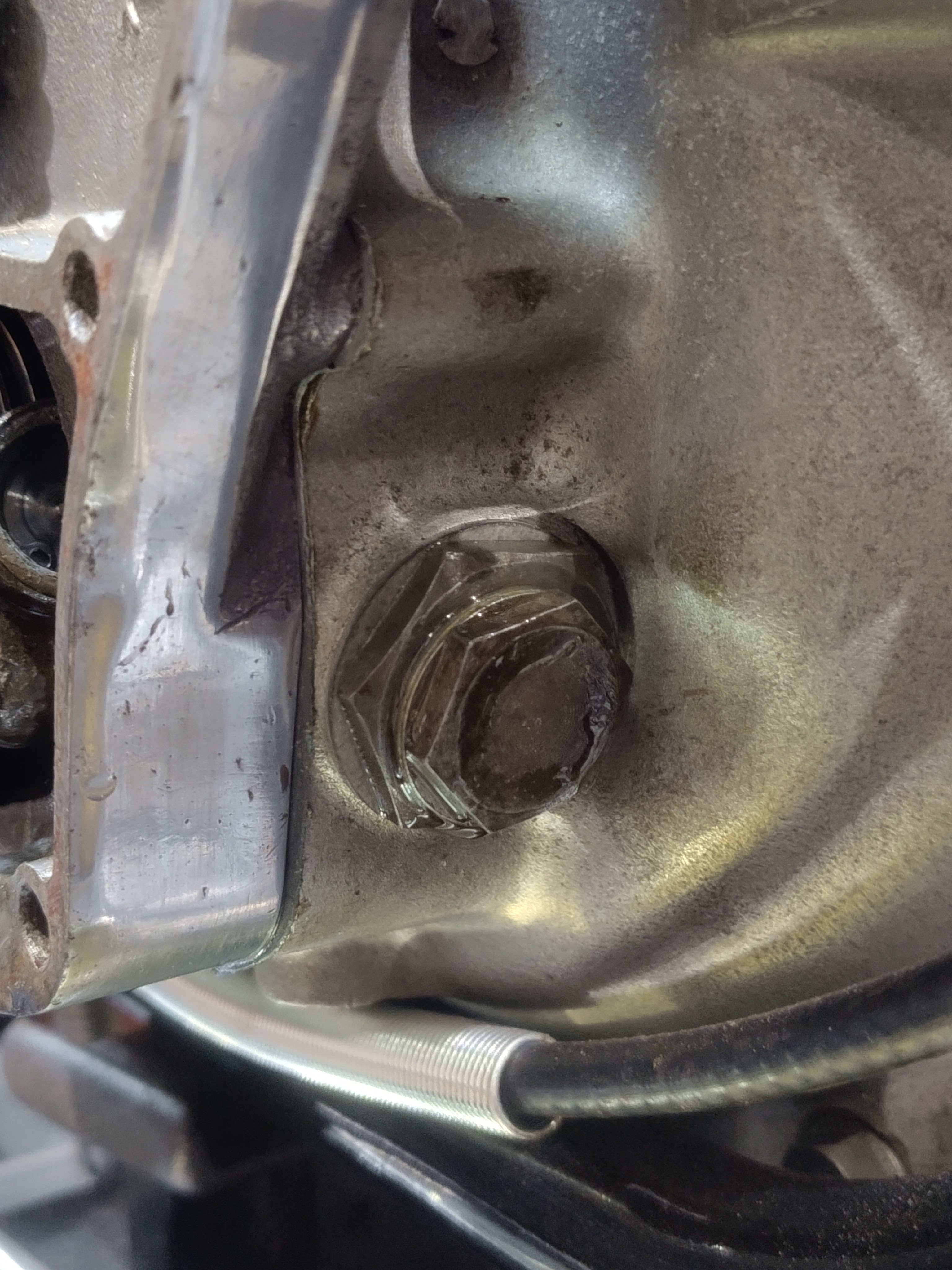
It's dry but not very hard. I scrape the paint off the gasket faces with a Stanley knife blade, and set about cleaning the bolt holes with a 5/16" plug tap. Apart from this damaged one, they are all in pretty good shape.


Next stop, put the valves in. We know that these fit, because in the last episode we ground them in so this time it is a matter of fitting the valves, Halite washers, spring seats, springs, spring tops and collets. Collets are a bit fiddly to get in, so the best thing to do is put a lump of grease on the stem and then introduce your spring compressor. When you have the spring compressed, fit the collets with a small pair of pliers, tweezers or a chopstick with a bit of grease on the end:


Push them into place with the stick and slowly, gradually, gently release the spring compressor. Tradition tells us to tap the valve stem with a hammer to make sure the collets are seated and the valve/spring assembly is secure.

Next, check the head seal to the barrel. These engines have no head gasket, but the barrel is machined with a spigot which is ground into the head with grinding paste; the area around the spigot is machine a few thousandths deeper so the pressure from the head bolts is born by the spigot alone, sealing the joint. When you are happy that you have a clean joint all the way around the spigot, you can think about putting the head on - but before you do, you need to sort out the pushrod tubes and their seals.

This is the bottom seal - the old, compressed black one and a new one from AOMCC Singles Spares:


Here's the top seal. You see there is a shorter spigot here, which fits around the spigot pointing downwards in the head. I've assembled these dry, with no sealant:


With the pushrod tubes standing in the crankcase, you can drop the head in place, watching the pushrod tubes settle onto the spigots at the top. Next you can drop the 3/8" CEI head bolts in - which I have previously cleaned on the wire wheel. Tighten these down firmly - there is no recommended torque figure. when that's done, the pushrods can go in. When I dismantled the bike, I stored the inlet and exhaust valve gear separately, so I could ensure they all went back in the same place.


Next I took the opportunity to refit the exhaust, with Threebond 1215, and the carburetter - again with Threebond and a new gasket.


Don't forget to put the little caps back on the valve stems:


Next, you can seal the new gaskets (I'm using Draganfly's new aluminium gaskets) and fit the rocker boxes. Be careful with the bolts - three are the same length (about 2 5/8") but one, the one above the pushrod, is longer - 2 7/8". The one shown in this picture is wrong - it's a short one. The danger of this is that you will pull the thread if you overtighten it.


This looks easy doesn't it! What you can't see in this picture is that I had refitted the exhaust rocker box without aligning the rocker in the top of the pushrod. Later, when fitting the decompressor I found it wouldn't work, and I had no compression. What was happening was that the misplaced rocker was holding the valve open, and preventing the eccentric pin on the decompressor reaching the pad on the rocker. Secondly, one of the long rocker box bolts is missing from the exhaust rocker box, so that's two I have to find.

I've now managed to fit both rocker boxes without missing anything out! I've added the rocker oil line, and this time I have fitted a cable tie as shown in the parts book for this bike - it's very unusual to see these fitted.

There is still a rocker box bolt missing (two actually), which I will have to make. I've used the opportunity to introduce some oil into the rocker box through this hole - this is not normally possible, but recall that this hole has a chunk broken out of the head and so provides a passage from the bolt hole into the head and down into the pushrod tube. The objective is to get some oil onto the camshaft.