Showing posts with label battery. Show all posts

Tuesday, 14 April 2026

SQ4 - batteries

  For the record, let it be known that I have today fitted a second battery to the system on the Square Four. This returns it to the layout that we ran for the first 7 years or so of its time in service. We now have 19 amp hours of capacity extended from the 12 amp hours we've been running for the last year.

We are back to running these VRLA batteries again: 

A few miles run later in the day showed one-kick starting, there is no fuel leak and the idle is fine. The ammeter showed a charge; the battery monitor also showed a charge and did not go out of the green zone. Since most of the run was quite slow, perhaps I should not be surprised that the battery charger spent a little time returning the batteries to full charge at the end of the day?

Tuesday, 7 April 2026

SQ4 - a little investigation

 Of course, a broken motorcycle can’t be left for too long, especially when your daily rider has been persuaded from your grasp.

There were a few problems to investigate, possibly associated:

  • There was a carburetter leak, or possibly flooding 
  • The battery indicator was showing far too much red, considering the 60 miles the bike traveled yesterday 
  • The bike refused to start twice yesterday, needing pushing to the top of a hill and roll-starting 

Putting the CTEK on the battery had it charging normally, but it was very flat:


But why so flat? According to the ammeter, the battery does charge and indeed, it was charging on the way home. I did notice the ignition had been left on as Tom had complained the engine wouldn’t idle and it had died when he arrived. I currently believe this has more to do with the battery than anything else.

There is no leakage from the battery with the engine not running and you can measure normal currents with lights on, though with the LEDs fitted to this bike these are minimal. The ignition circuit draws 400 mA without the engine running - I think it would be a good idea to try this with the engine running.

I've also realised that the red spot ammeter doesn't show very much deflection at all - I calibrated the one on the Huntmaster against my bench power supply and there is a lot more movement. I wonder if the Square Four has a 30-0-30 ammeter.

A simple test with a 35 watt bulb revealed that the ammeter appears to be 15-0-15 - while I was doing this test the multimeter was reading 5 amps.


As a first step towards sorting the fuel leak, I removed the drain plug/main jet holder and finding no new fibre washer of the right size, sealed it with a wipe of Threebond 1215. That fixed the leak, and there is no evidence of flooding. 

Amelia started first time like she always does.

As to the idle, I don’t know yet as I haven’t got it warm enough to close the bi-starter.

Sunday, 1 December 2024

FH - where are we again?

Doesn't she look great?


  A few weeks after the last catching up post I'll write another one. It might be a bit boring for some but it's very useful to have a list of where you are and what you've got left to do, especially as there are some tiny things that get forgotten very easily - for example I've put the new gearbox inspection plug on the rocker box, and now I can't find the rocker box inspection plug...

I’ll summarise where I am in order to work out what to do next:

  1. Engine: the engine is basically finished. Ignition timing is done, the oil lines are connected up and I have done the circulation on the power drill and proved that the lubrication system works properly. The next step is to finish the head steadies for which unfortunately I have to lift the rocker box slightly in order to get the nuts on. Thinking about this again, I just fitted the drive side exhaust and I'm well on the way to fitting the timing side exhaust and both of these interrupt access to the head steadies...
  2. Oil System: the lubrication system is working as I said but I've realised the oil tank will have to come out because one of the seat bolts is missing; and actually the oil tank isn't bolted in properly. There's also a small leak coming from the return filter.
  3. Fuel system: carburettor needs gasket sealant and the air cable shortening.
  4. Ignition system: HT leads need to be terminated into their caps, and the plugs need to be screwed in.
  5. Gearbox: so today I have put the kickstart case back on as you will have seen in a previous post, but I seem to have lost the inspection cap. I need to fit the gear position indicator, fill the gearbox with oil and solder a nipple onto the clutch cable but then we'll be done.
  6. Clutch: I'm fairly confident that the clutch is completely finished, apart from fitting the dome.
  7. Chains: primary is in, tensioned but not oiled; secondary has a dummy fitted.
  8. Exhausts: the timing side is fitted but the drive side is still loose. Both of the finned clamps need to have screws made up on the lathe.
  9. Electrics: the electrical system is more or less working with a couple of exceptions. The instrument panel is waiting for the speedo to come back from Chronometrics, the battery is still wired negative earth while the dynamo has not been flashed to suit. The voltage regulator enclosure still contains the original RB108 components which will need a modern conversion to suit the VRLA batteries.
  10. Control Cables: the throttle and front brake cables are finished; the air cable needs the nipple moving about half an inch and the clutch cable needs both nipples replacing and the inner cut to suit.
  11. Wheels & tyres: these are parked until the machine is running. I might have a look at the front brake shortly, just to clear it out before I am tempted to ride the bike around the yard!
That about sums it up. Cables next?

Sunday, 10 November 2024

FH - more wiring

 Wiring jobs are plodding on at the moment. This next picture shows the splice that I have made to provide a battery feed to the horn and stop switch. It's quite difficult to follow the original wiring diagram and make all of these connections at the battery terminal with modern VRLA batteries with their tiny spade terminals.

It's soldered and covered with heat shrink sleeving.


Here is a view of the rear brake light switch. Behind the oil tank, in front of the mudguard and behind the toolbox is a very difficult position to get to to put that bullet connector in. Ariel clearly assembled the switch and the wiring before the oil tank went on - which reminds me, there is no seat bolt above the oil tank, so the tank will have to come off again!


You can also see in this picture that the rocker feed oil line is not very well fitted to the stub on the oil tank. I pushed this on a lot further.

This next one shows the wiring for the regulator, complete with the seal, clamp and split bullets:


That's the battery area complete. For the record, this is wired negative earth which means I will have to flash the dynamo at some point.


For some reason the battery lids are moulded with four cable access slots. This is because they are a copy of the original moulding which had to accommodate large Bakelite knobs for the battery terminals. I've filled two of these holes with black hot-melt glue.


Next stop, wiring up the dynamo. You can see the dynamo D connection on the left, as it connects directly to one of the brushes. The field F connection on the other side connects to one of the white field cables going into the body of the dynamo.

I oiled that felt before I closed the dynamo up.


That's the dynamo wiring sealed up. 


The last job today is to finish the wiring to the rear lamp. These are the finished cables from the harness with Japanese bullet connectors for the stop switch and rear lamp and a crimped and soldered eyelet for the earth.


The earth wire is attached to one of the rear lamp fixing bolts. 


Monday, 2 November 2020

SQ4 - low batteries and flashing lights

The batteries on the SQ4 are now seven years old and are coming to the end of their life, as witnessed by a complete failure to start earlier this year, remedied with the CTEK charger, and a short trip out a few days ago. This one was odd - I had left it idling on the bi-starter to warm up and all was fine (though of course at that speed it wasn't charging). I then took it out and it had no power, eventually dropping onto three cylinders within a few hundred yards of the house - I travelled 1/2 a mile in all, none of it at high enough speeds to charge the battery.

Getting home, the multimeter showed my batteries were down to 5.5 V or so. New batteries are on the horizon!

In the meantime, picking up on a thread in the AOMCC forum I had bought a battery condition monitor from Gammatronix:

I've chosen to fit it in the top of the dummy battery box. It fits in a 14mm hole which I cut with a cone drill.


I've sealed it with some silicone on the outside:


It's also protected on the inside with some pvc sleeving:


Once you have fitted the battery monitor and have wired it up (even temporarily - it remembers it's settings) you have to programme it. This is by a simple sequence of button pushes. I have it set to 6V, Map #3:


There's a further map #6, which is for low current applications and shows a slow red, yellow or green blink according to voltage level.

Here is a very exciting video of a LED flashing green. Tell your friends, it is riveting stuff: 

Eagle eyed readers will see the CTEK charging connector I have fitted in the background. 

The battery monitor is wired in using a long twin core cable, so that I can remove the dummy battery box lid and lay it on the seat for battery or fuse box access.


Saturday, 8 September 2018

Portable Power Supply

Some of you may know that I tinker around with solar power from time to time and that in fact my workshop is 'off-grid'. One of the features of a lifetime spent tinkering with stuff is a lot of spare bits lying around, so when a friend was looking for a lighting system for her allotment shed and summer house I thought I could come up with something quite easily.

I had a 86W panel and a small car battery knocking about (as you do - they were part of the evolution of my workshop solar power system), so I would not have to spend much money. I also had a simple panel controller, which essentially sense battery voltage & connects the panel if the voltage is below a set point and disconnects it when it goes above the set point - pretty basic; no MPPT here.

What I needed was something to unite it all into a simple portable unit. This came in the form of a bit of an old kitchen unit and some pine offcuts:


I used the little router to cut a slot at the back:


This accommodates the foot of the battery. I sized it to suit the largest battery I had, to 'future proof' it a little. You can see how the foot of the battery is trapped in the groove:


The other foot is trapped under this little bar, made from 3 mm cold rolled sheet and retained with two M6 wing nuts:


Here's the battery in place with the controller:


Here I've added a simple modified sine wave inverter. It gives 200 W at 220 VAC, so you can charge your phone from it.


Here it is with the wiring completed. The six terminals top left are for the solar panel and for two 12V outputs. Lower down, there is a higher current termination for main battery cable, voltage sensor and feed to the inverter.


The inverter provides 200W at 220 VAC - that's about an amp, which translates to about 20 A on the DC side; I can run a 60Ah battery for 36 minutes at that rate, assuming my maximum allowable discharge is 20% - with a deep cycle battery I could increase that, and the frame will carry larger batteries.

Friday, 29 September 2017

Updating the Lucas MCR1 Voltage Regulator

The little Lucas MCR1 is used with the short Lucas E3 dynamos, like the one fitted to my W/NG.

I like my bikes to look period, but I don't mind updating them to improve performance if there's no visible sign of it externally. The MCR1 was not working, and since I have a similar electronic regulator on my SQ4, which has been looking after my charging system for years, I have no qualms about updating this one.

The update to the SQ4's MCR2 Regulator is shown in a previous post. Today we are looking at the MCR1.

I am going to fit a modern V-Reg 2b dynamo regulator which is designed to replace the mechanical regulator with modern, reliable semiconductors, can handle up to 100W at 6V and even more for the 12V version provided the dynamo is capable of delivering this power. This device is proven and reliable and is available in Positive or Negative earth. 

New features of the 2b include: 
  • Current limit to the field winding, allows excellent performance when using a 6V dynamo on a 12V system while not straining the dynamo. 
  • Tougher electronics, with the introduction of higher energy spark suppression to reduce spikes generated by the dynamo. Improved "thermal foldback" which progressively reduces output power if the regulator gets too hot, indirectly limiting the dynamo from excessive current. 
  • Better servo loop stability, with new electronics which 'predict' when the output voltage is nearly correct and control the field current earlier.
Mine came from AOServices, who manufacture the V-Reg. You can buy them from a number of other suppliers, but Alan Osborn at AO provides a fine customer support service here in Norfolk. When you order your regulator, you must specify the polarity - a positive earth regulator uses different components to a negative earth regulator, and you cannot convert them. However, the same V-Reg 2b will run a 6V system or by cutting a simple wire link will run a 12V system.

Here it is, with the original 1942 MCR1 quaking in the background. That little green wire is the 6V/12V link.


To get inside, undo the wire clip and remove the cover to reveal the coils & terminals. We'll be removing those coils in a moment:


Here's the underside, showing the two screws holding the bobbins in place:


The cover is stamped with the month and year of manufacture:


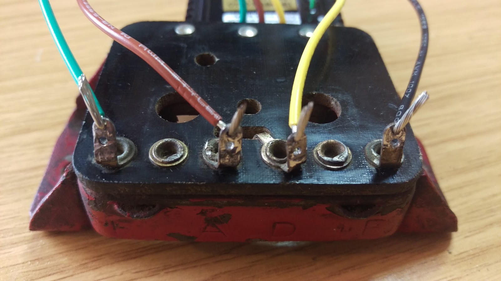
Now to start work. The original D terminal screw is soldered in place - peel the solder away and remove both of the visible screws:


The coils will now be loose. Cut all the wires to each of the terminals, being careful not to damage the terminals:


Lift the coils away:


Remove the clip. It's going to get in the way:


Clean up thoroughly. This is a glass brush - it's quite abrasive and does a fine job of cleaning the terminals and the muck around them. Clean the rest down with a spirit wipe.


Take a small soldering iron (this one is a variable 60W iron) and remove the solder and any remaining strands of original wire from the terminals. You can use a solder sucker if you need to.


Then clean the terminals with your glass brush or a sharp knife. Make sure the holes are clear.


Cut off the eye underneath the regulator. It's connected to the D terminal - you don't want charging voltage escaping into the rain. It easier to do this from above, unlike my picture:


Now, the MCR1 is a lot smaller than the MCR2 we upgraded for the SQ4, and the mounting for the V-Reg 2 needs to change. Here I'm using four adhesive pads to stick the V-Reg to the Tufnol insulated base of the MCR1. Don't stick them down yet.


So here we have bared the wires and carefully threaded them through the holes in the correct terminals. BE CAREFUL! you don't want to get this wrong and destroy your new regulator. Bend the bare ends to align with the terminal and increase the strength of the joint.


Now solder the wires in place. Make sure you have heated the terminal effectively, so the solder flows cleanly and wicks into the conductor strands. Don't melt the solder directly with the iron, but let the work heat the solder - that way, you know the wire or terminal is hot enough to make a good joint. I'm using electricians cored solder here:


Coil the wires above the regulator such that they stay within the MCR1 cover, and retain with a small tie-wrap. We don't want to introduce a fatigue failure or have these wires trapped somewhere.


All done:


Finished, with no visible changes:


And the bike is charging:


Monday, 14 November 2016

W/NG Battery

As I've mentioned before, I have a very nice continental-looking battery box that came with the bike. Here it is:


The original PUW7E battery specified has a 10 Ah capacity, which is the peculiar way in which our industry has chosen to illustrate the energy capacity of a battery - it means it is capable of delivering a current of 10 Amps for an hour, or 20 Amps for half an hour, or 5 amps for 2 hours - you get the idea.

My little Lucas E3HM dynamo gives me 40W at some speed, but I don't know what speed - something like 6.5 A So, in order to use my bike for a reasonable period of time without being charged (for when I choose to ride at 10 mph in a traffic queue on the M25 (when did you last see a W/NG do that?)) I need a battery of sufficient capacity to deliver sufficient current for the time I am riding so slowly that the battery is not charging, without running flat and plunging me into darkness.

So how much current do I use? Let's work it out:
  • my headlamp will use up to 55W, which at 6V needs just under 10 Amps to deliver the power (Power, W = Potential Difference V x Current A)
  • my tail lamp will use 5W, which needs another Amp
Which gives us around 11 Amps, allowing for infrequent use of the stop light and horn. A 10 Ah battery will be flat in 54 minutes. Reasonable? No. The headlamp bulb is too big. What about this:
  • a smaller headlamp using 35W, which at 6V needs just under 6 Amps to deliver the power
  • my tail lamp is an LED, which is negligible
I don't have a Lucas PUW7E battery, nor am I likely to find on - and in fact, why would I want a rubber box full of sulphuric acid attached to my bike? I will use the Yuasa 12 Ah VRLA battery I have on the shelf...

That will give me 2 hours of operation of a 35 W halogen before it goes flat. Since a year or so into having the Bantam, Beattie has been using a sealed lead-acid battery - the electrolyte is treated to form a gel, so it can't flow out, and the chemistry is altered somehow (I'm not that clever) so that when the battery is charged and would normally produce free oxygen & hydrogen, the gases recombine as water, replacing the lost liquid in the cell. This is really neat for a motorcycle, because it means you can fit them wherever you want (they are really small), they don't drop nasty acid all over your bike (how many rusty battery carriers have you seen?) and because they are made for things like burglar alarms, they are really cheap. The SQ Four has had two of them on board for a few years now.

The downside is you cannot abuse them as you can a traditional wet battery - if you overcharge them and lose the electrolyte, you can't replace it.

The thing is, I came to use one of these things the first time because I realised the rudimentary (putting it kindly) charge control system on the Bantam was boiling the original wet battery - so I added a modern solid state regulator/rectifier (from the marvelous Rex Caunt Racing) and was able to use a gel battery. The one on the Bantam is tiny - about 3.4 Ah I think, at 12 V, and has coped perfectly for several years. It even remains charged through the winter, something the old wet battery could never do. The SQ4 has two, combined to give 20 Ah and controlled with an V-Reg regulator.